
Camera module and camera module assembly method

A camera module and assembly method technology, applied to the camera body, camera, installation, etc., can solve the problems of the lens deviating from the focus position, high requirements for back focus, and reducing the assembly efficiency of the camera module

Active Publication Date: 2013-03-27
HONG FU JIN PRECISION IND (SHENZHEN) CO LTD +1
View PDF6 Cites 26 Cited by
  • Summary
  • Abstract
  • Description
  • Claims
  • Application Information

AI Technical Summary

Problems solved by technology

However, in general, the curable adhesive generally needs to be cured by ultraviolet radiation, and other mechanisms of the camera module are usually arranged on the substrate, which will block the ultraviolet light from irradiating the curable adhesive, thus prolonging the curing time of the curable adhesive , reducing the assembly efficiency of the camera module
[0004] In addition, the camera module has generally adjusted the focus before the active alignment, and adjusted the lens to the focus position along its axis. However, adding curable glue will change the position of the lens along the axis of the lens, causing the lens to deviate from the focus position. , the imaging quality of the image camera module, and the camera module cannot be refocused after active alignment, because refocusing will change the inclination angle of the lens again, making the previous active alignment invalid
[0005] If the focus of the camera module is adjusted while actively aligning, the position of the lens along its axis cannot be adjusted for a long distance due to the difficulty of maintaining a large thickness of the uncured curable adhesive (generally 0-120um between), which requires the tolerance of the back focus of the camera module to be small (limited to 120um), that is to say, the requirement for the back focus of the camera module is relatively high, and this will increase the manufacturing cost of the camera module

Method used


Image

  • Camera module and camera module assembly method
  • Camera module and camera module assembly method
  • Camera module and camera module assembly method

Examples


Embodiment Construction

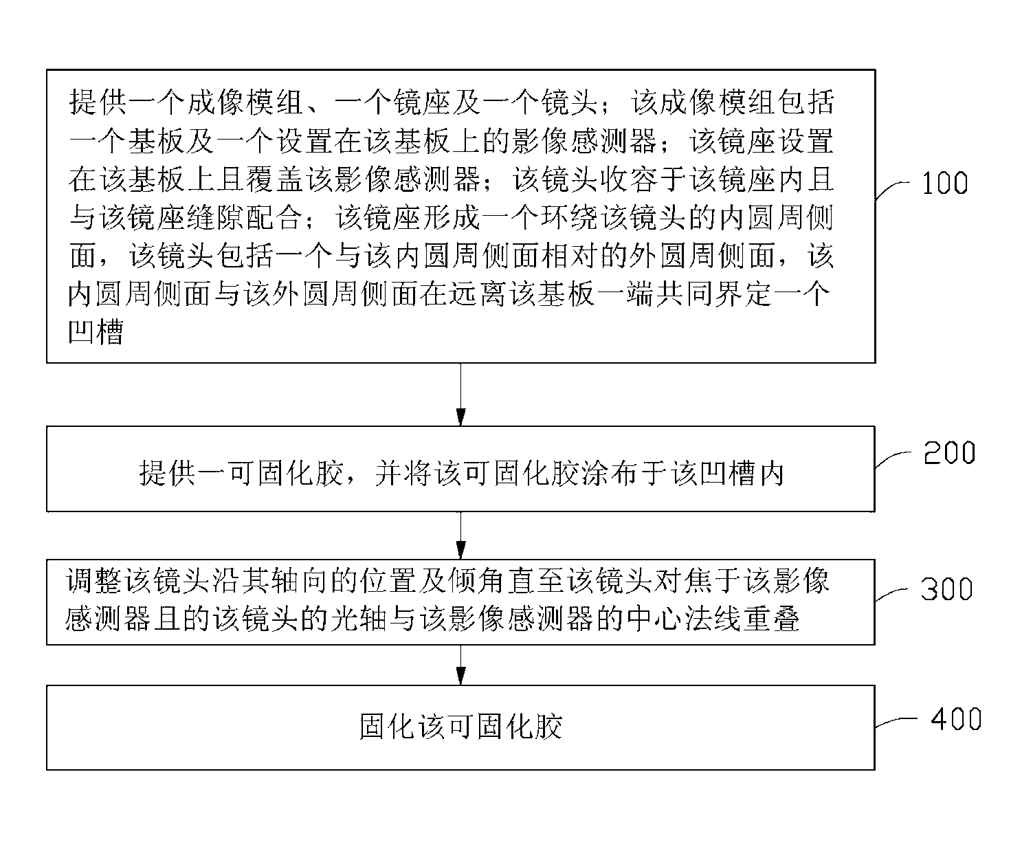
[0026] see figure 1 and figure 2 , the camera module assembly method of the first embodiment of the present invention includes:

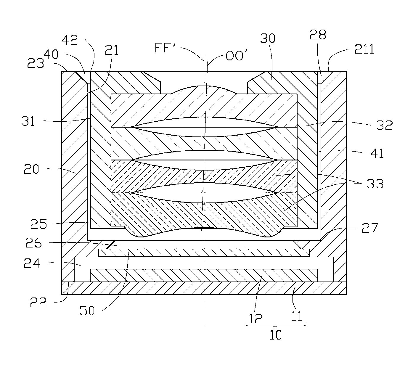
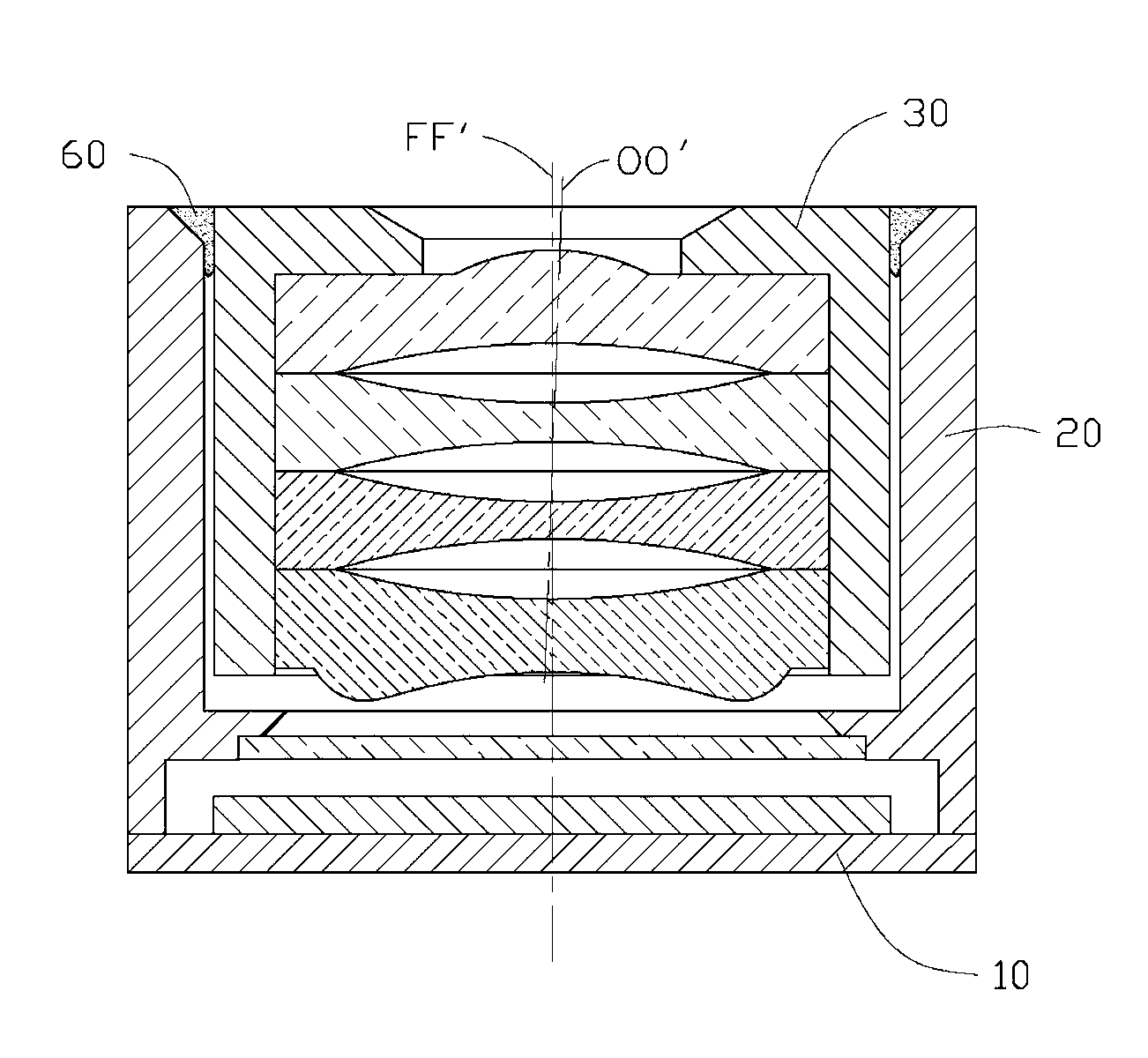
[0027] Step 100 : providing an imaging module 10 , a lens mount 20 and a lens 30 . The imaging module 10 includes a substrate 11 and an image sensor 12 disposed on the substrate 11 . The mirror base 20 is disposed on the substrate 11 and covers the image sensor 12 . The lens 30 is accommodated in the mirror holder 20 and fits in a gap with the mirror holder 20 . The mirror holder 20 includes an inner peripheral side 21 surrounding the lens 30 , the lens 30 includes an outer peripheral side 31 opposite to the inner peripheral side 21 , the inner peripheral side 21 and the outer peripheral side 31 are away from the substrate 11 The ends together define a groove 40 .

[0028] Specifically, the mirror base 20 includes an image-side end surface 22 attached to the substrate 11 and an object-side end surface 23 opposite to the image-side end surface ...


PUM


Abstract

The invention provides a camera module assembly method. The camera module assembly method includes providing an imaging module, a lens base and a lens, providing curable adhesive, coating the curable adhesive in a groove which is jointly defined at one end distant from the substrate by the circumference side of the lens and the inner circumference side of the lens base; adjusting the axial position of the lens and the inclined angle until the lens focuses the image sensor and the optic axis of the lens is superposed on a central normal line of the image sensor, and curing the curable adhesive, wherein the imaging module comprises a substrate and an image sensor arranged on the substrate, the lens base is arranged on the substrate and covers the image sensor, and the lens is held in the lens base and is in clearance fit with the lens base. By the camera module assembly method, assembly efficiency can be improved, and imaging quality of an assembled camera module is guaranteed. The invention further provides the camera module.

Description

technical field [0001] The invention relates to a method for assembling a camera module and the camera module. Background technique [0002] A camera module generally includes an imaging module, a lens mount and a lens. The imaging module includes a substrate and an image sensor disposed on the substrate. The mirror base is arranged on the substrate and covers the image sensor. The lens is held in the mirror mount and aligned with the center of the image sensor. Although they are directly or indirectly arranged on the substrate, however, limited by the molding and assembly accuracy, the inclination angles of the image sensor and the lens relative to the substrate are usually inconsistent, causing the center normal of the image sensor to deviate from the optical axis of the lens. As a result, the image formed by the camera module may have defects such as half-edge blur. [0003] In order to solve the above problems, it was proposed to apply curable glue on the connection ...

Claims


Application Information

Patent Timeline
IPC IPC(8): G02B7/02G03B17/12
Inventor 许信彦
Owner HONG FU JIN PRECISION IND (SHENZHEN) CO LTD
Learn More