Current-limiting protector for electrical fire prevention

A technology of protectors and current transformers, which is applied in the direction of overcurrent protection, electrical components, emergency protection circuit devices for limiting overcurrent/overvoltage, etc., and can solve arcing ablation, short circuit spark fire , slow movement speed and other issues, to achieve the effects of easy expansion of current, elimination of electrical sparks, and fast switching speed

Active Publication Date: 2015-06-24
SHANGHAI CHENGJIA ELECTRONICS TECH
View PDF9 Cites 1 Cited by
  • Summary
  • Abstract
  • Description
  • Claims
  • Application Information

AI Technical Summary

Problems solved by technology

[0004] 1. Lack of quick response ability: The electromagnetic trip circuit breaker has the problem of slow movement speed when it is completely disconnected during the switching process, and there is also a discharge phenomenon, which is called arcing, so the switch of the electromagnetic trip circuit breaker The time is generally at the millisecond level or even longer. When a short-circuit fault occurs, the existing fire monitors lack the ability to quickly break, and it is often too late to quickly cut off the line, resulting in a sharp increase in the short-circuit current instantaneously, exceeding dozens of times the rated operating current. As a result, the wire will heat up, melt or burn, and short-circuit sparks will be generated to cause a fire
[0005] 2. Lack of real-time current limiting function: Although existing fire monitors can detect faults such as residual current, overcurrent, short circuit, overtemperature, smoke, and flame, if the most dangerous fault occurs, the existing fire monitor Due to the lack of rapid control capability, the fire monitor cannot immediately limit the expansion of short-circuit current, which will cause a sharp increase in short-circuit current and cause electrical sparks to cause fires
[0006] 3. Limited to post-event alarm: Due to the long breaking time of the existing fire monitor, even if a short-circuit fault is found, but because of the slow response speed of the system, it can only stay in the post-fire alarm
Although some fire monitors are linked to the sprinkler system, they are only for fire fighting after the fire
[0007] 4. Short service life and poor reliability: Because the existing fire monitors use electromagnetic circuit breakers for breaking protection, the mechanical contacts of electromagnetic tripping circuit breakers will produce jitter and flashover when switching, which will aggravate the damage on the contact surface. Oxidation, increase contact resistance, poor contact faults, flashover ablation contacts or even melting, shortening the life of the circuit breaker and causing the circuit breaker to fail
[0008] 5. There is a potential fire hazard due to contact flashover: the existing fire monitor uses an electromagnetic circuit breaker to perform breaking protection, and its contact arc extinguishing effect is relatively poor, resulting in flashover, which is easy to ignite combustibles, so there is a fire hazard
However, the thyristor switch still has the defect of slow switching process, and the response speed is still at the millisecond level. When an electrical short circuit occurs, it is still too late to quickly cut off the line, causing the short circuit current to increase rapidly until a fire is caused.
In addition, the thyristor switch also has a tube voltage drop of 1-2V, so there is a problem of large power consumption.
[0010] Therefore, although the current electrical fire prevention monitoring equipment of the prior art can detect faults such as electrical short circuit, circuit overload, leakage, smog and high temperature, it is only limited to post-event alarm and control after the fault occurs, and cannot timely suppress the immediate occurrence of an electrical fire. occur and expand

Method used


Image

  • Current-limiting protector for electrical fire prevention
  • Current-limiting protector for electrical fire prevention
  • Current-limiting protector for electrical fire prevention

Examples


Embodiment Construction

[0037] In order to make the above objects, features and advantages of the present invention more comprehensible, specific implementations of the present invention will be described in detail below in conjunction with the accompanying drawings.

[0038] In the following description, numerous specific details are set forth in order to provide a thorough understanding of the present invention. However, the present invention can be implemented in many other ways different from those described here, and those skilled in the art can make similar extensions without violating the connotation of the present invention, so the present invention is not limited by the specific implementations disclosed below.

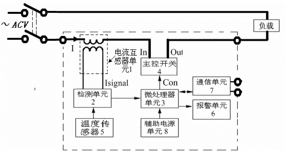
[0039] see figure 1 , the present invention provides an electrical fire-proof current-limiting protector, comprising:

[0040] A current transformer unit 1, the current transformer unit 1 is used to detect the AC current I in the main circuit in real time, and respectively induce a...


PUM


Abstract

The invention provides a current-limiting protector for electrical fire prevention, which comprises a current transformer unit, a detecting unit, a microprocessor unit and a master control switch unit, wherein the current transformer unit is used for detecting alternating current in a main circuit in real time and outputting a corresponding current signal in an inductive manner; the detecting unit is used for collecting, preprocessing and outputting the current signal; the microprocessor unit is used for processing the current signal and a working temperature signal in a machine, presetting a segmentation delay parameter and a superheating temperature parameter and judging the received preprocessed current signal as short-circuit current or overload current to output a rapid breaking instruction or to carry out a segmentation delay current-limiting instruction respectively; and the master control switch unit connected with the current transformer unit, the microprocessor unit and a load and used for switching on and off the main circuit according to a received control instruction of the microprocessor unit. The current-limiting protector can avoid the continuous increase of the short-circuit current effectively due to a rapid current-limiting protection function and can prevent fires caused by the heating, fusion and burning of wires and an electrical spark generated at a short circuit part.

Description

technical field [0001] The invention belongs to electric and electronic emergency protection circuit devices, in particular to an electric fire-proof current-limiting protector. Background technique [0002] Among the fires caused by electrical circuit faults, the fires caused by circuit short circuit and overload current faults are particularly prominent. The so-called circuit overload current means that the current in the circuit exceeds the rated working current. Overcurrent for a long time will cause the wire to heat up, melt and burn, or even short-circuit faults. Once a short circuit occurs in the circuit, the current in the circuit will increase sharply, causing a surge in energy at the short circuit, far exceeding the tolerance of the electrical circuit, causing the wire to heat up, burn, and cause a fire due to electrical sparks at the short circuit. [0003] Various fire alarm monitors currently used in the market generally have functions such as residual current ...

Claims


Application Information

Patent Timeline
Patent Type & Authority Patents(China)
IPC IPC(8): H02H9/02H02H3/08H02H5/04
Inventor 刘中元陈立民蔡祖卫潘耕艺陈大方顾华
Owner SHANGHAI CHENGJIA ELECTRONICS TECH
Why Eureka
Try Eureka