A magnetic resonance engine device and method

A magnetic resonance and engine technology, applied in the directions of magnetic resonance measurement, magnetic variable adjustment, control/regulation system, etc., can solve the problem of high signal strength, loss of polarization degree of hyperpolarized inert gas, and density of hyperpolarized inert gas signal itself Low-level problems, to achieve the effect of enhancing the magnetic resonance signal and increasing the sample density

Active Publication Date: 2014-10-15
WUHAN INST OF PHYSICS & MATHEMATICS CHINESE ACADEMY OF SCI
View PDF10 Cites 0 Cited by
  • Summary
  • Abstract
  • Description
  • Claims
  • Application Information

AI Technical Summary

Problems solved by technology

[0005] However, the hyperpolarized noble gas NMR signal intensity detected in the experiment is often not as high as the signal intensity when it was generated
The main reasons include: 1) affected by the cleanliness of the collection device, pipeline, etc., material types, and paramagnetic substances, the polarization degree of some hyperpolarized inert gases will be lost; Due to the space limitation in the noble gas pipeline, the arriving hyperpolarized noble gas signal itself has a low density; 3) Although the optically pumped spin-exchange working gas used in the experiment is a high-pressure mixed gas, such as 5atm 8 , but usually the composition of the gas mixture mainly includes the pressure-expansion gas 4 He, fluorescence quenching gas N 2 , while the inert gas content is only 1 to 3%, that is, the amount of hyperpolarized inert gas produced is limited

Method used


Image

  • A magnetic resonance engine device and method
  • A magnetic resonance engine device and method

Examples


Embodiment 1

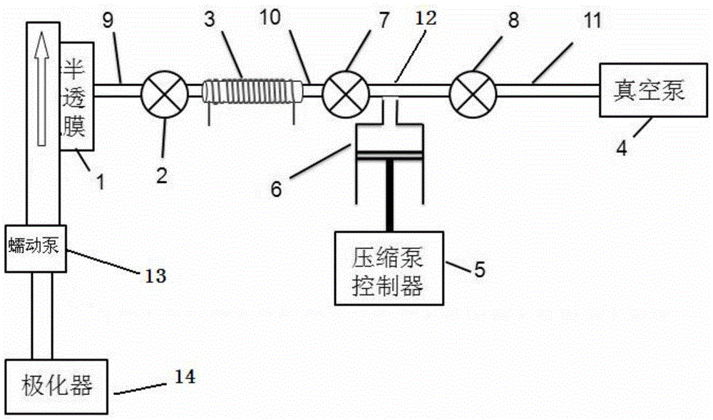
[0028] Such as figure 1 As shown, a magnetic resonance engine device includes a first valve 2, a second valve 7, a third valve 8, a vacuum pump 4, a compression pump 6 and a compression pump controller 5, one end of the first valve 2 and one end of the first pipeline 9 The other end of the first pipeline 9 is provided with a semi-permeable membrane 1, the first valve 2 and the second valve 7 are connected through the second pipeline 10, the second pipeline 10 is provided with a detection coil 3, the outlet of the compression pump 6, the first The second valve 7 and the third valve 8 are respectively connected to the three channels of the tee 12 , and the third valve 8 is connected to the vacuum pump 4 through a third pipeline 11 .

[0029] A magnetic resonance engine device further includes a polarizer 14 and a peristaltic pump 13, the polarizer 14 is connected to the peristaltic pump 13, and the peristaltic pump 13 is connected to the first pipeline 9 through the semipermeabl...

Embodiment 2

[0033] Hyperpolarized noble gases are 129 Xe,

[0034] After the experiment started, at first the first valve 2, the second valve 7, and the third valve 8 were all kept open, and the vacuum pump 4 was started to suck all the air in the pipeline of the whole system to keep the vacuum degree lower than 4psi. If the air is drawn outside the system, the system will be in and maintain a negative pressure state. At this time, the piston of the compression pump 6 will be in its own state close to the three-way 12. When the system is in a vacuum state, close the third valve 8 to isolate the pipeline system from the vacuum system. Since the semi-permeable membrane 1 is a one-way chemical membrane, it can only allow 129 Xe gas molecules permeate, and when there is a pressure difference between the two ends of the semi-permeable membrane 1, when the dissolved hyperpolarized 129 Hyperpolarization in a solution of Xe 129 The Xe gas will pass through the semi-permeable membrane 1 and ent...

Embodiment 3

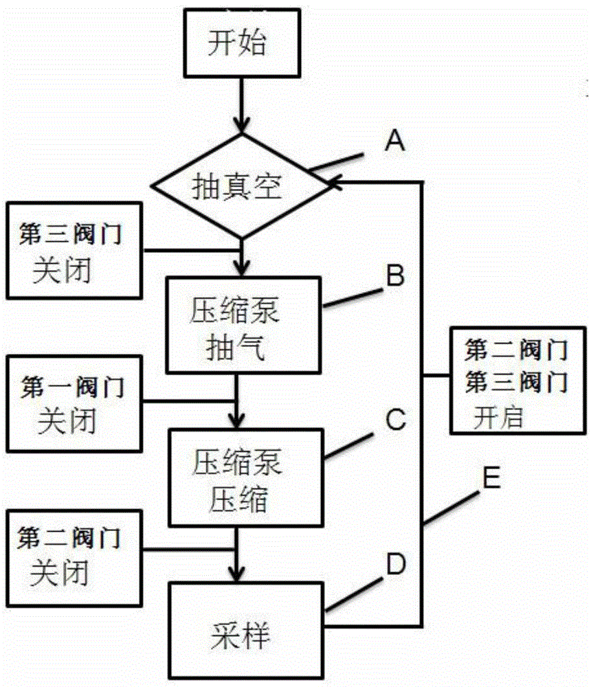
[0037] A magnetic resonance engine method, comprising the steps of:

[0038] Step 1 (A), open the first valve 2, the second valve 7 and the third valve 8, start the vacuum pump 4, until the vacuum degree in each pipeline and valve in the device is lower than 4psi, the piston of the compression pump 6 is driven by negative pressure. Suction to the process closest to the tee 12;

[0039] Step 2 (B), close the third valve 8, the hyperpolarized inert gas enters the first pipeline 9 through the semi-permeable membrane 1, the compression pump controller 5 controls the piston of the compression pump 6 to move away from the tee 12, and the hyperpolarized inert gas The polarized inert gas fills the volume space of the compression pump 6;

[0040] Step 3 (C), close the first valve 2, the compression pump controller 5 controls the piston of the compression pump 6 to compress in the direction close to the tee 12, and press the hyperpolarized inert gas into the first valve 2 and the second ...


PUM


Abstract

The invention discloses a device for a magnetic resonance engine. One end of a first valve is connected with one end of a first pipeline, the other end of the first pipeline is provided with a semipermeable membrane, the first valve and a second valve are connected with each other through a second pipeline, a detection coil is sleeved on the second pipeline, an outlet of a compression pump, the second valve and a third valve are respectively connected with three channels of a tee, and the third valve is connected with a vacuum pump through a third pipeline. The invention further discloses a method for the magnetic resonance engine, wherein hyperpolarization inert gases permeate into polyfluoroalkoxy (PFA) through the semipermeable membrane under the negative pressure state; a cavity space is gradually compressed; high-concentration gases are subjected to nuclear magnetic resonance sampling; and residual gases are extracted and discharged. The device is simple in structure and is convenient to operate, after the hyperpolarization inert gases are collected and compressed, through increasing the concentration of the hyperpolarization inert gas sample in the detection coil, the signal strength of the hyperpolarization inert gases can be further improved.

Description

technical field [0001] The invention belongs to the field of nuclear magnetic resonance spectroscopy, and more specifically relates to a magnetic resonance engine device and a magnetic resonance engine method, which are suitable for hyperpolarized inert gas nuclear magnetic resonance. Background technique [0002] So far, commercial nuclear magnetic resonance spectrometers have been very mature, typically products from companies such as Bruker in Germany and Agilent in the United States. The NMR spectrometer first applies an electromagnetic wave of a specific frequency to the sample in a strong magnetic field through a coil. After the sample absorbs the electromagnetic wave of a specific frequency and undergoes a relaxation process, it will radiate an electromagnetic wave of a certain frequency. The coil and electronic circuit can convert and process the electromagnetic wave radiated by the sample to obtain the final magnetic resonance signal. [0003] In recent years, the ...

Claims


Application Information

Patent Timeline
Patent Type & Authority Patents(China)
IPC IPC(8): G01R33/28
Inventor 周欣李昭孙献平叶朝辉刘买利
Owner WUHAN INST OF PHYSICS & MATHEMATICS CHINESE ACADEMY OF SCI
Why Eureka
Try Eureka