Combined vibration isolation mounting for subways

A combined, vibration isolation technology, applied in the direction of shock absorber-spring combination, shock absorber, spring, etc., can solve the problem of high cost of floating plate, achieve the effect of good long-term life, low cost and broad application prospects

Inactive Publication Date: 2013-03-13
FOSHAN BAJ ISO TECH
View PDF7 Cites 9 Cited by
  • Summary
  • Abstract
  • Description
  • Claims
  • Application Information

AI Technical Summary

Problems solved by technology

[0004] Steel spring vibration isolation bearings are mostly used in the floating slab structure of subways in my country. Due to the fatigue life requirements of the floating slab, steel springs are mostly imported, resulting in high cost of the floating slab

Method used


Image

  • Combined vibration isolation mounting for subways
  • Combined vibration isolation mounting for subways
  • Combined vibration isolation mounting for subways

Examples


Embodiment 1

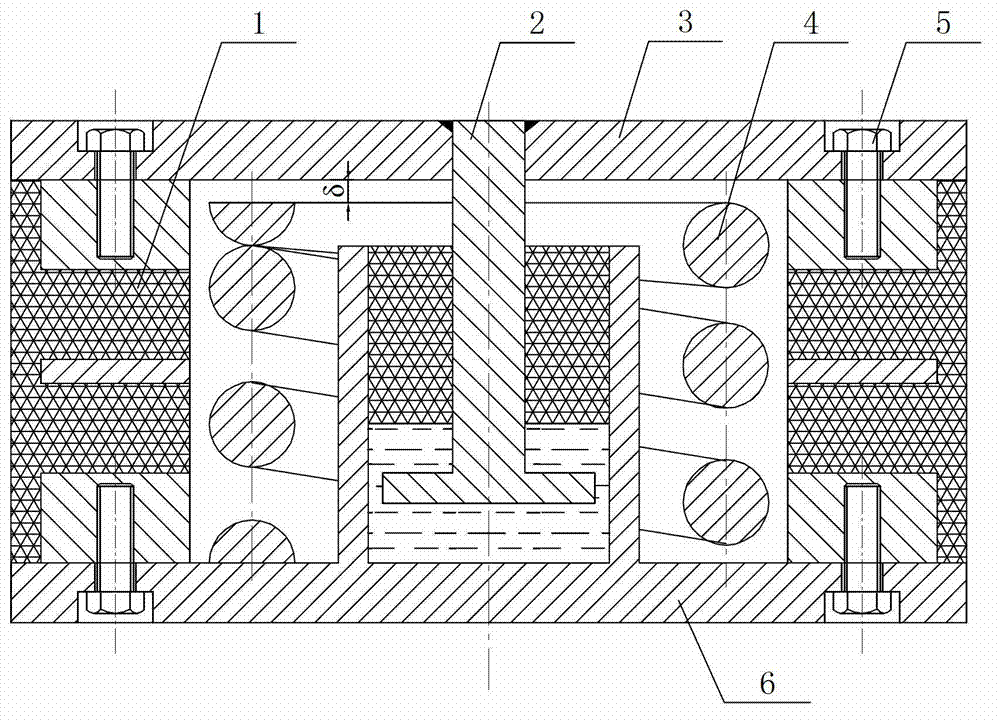
[0036] An embodiment of a combined vibration isolation device for subways of the present invention is as follows Figure 1 to Figure 3As shown, the vibration isolation device includes an upper coupling plate 3 at the top and a lower coupling plate 6 at the lower part, and it is characterized in that the vibration isolation device also includes a vibration isolation mechanism between the upper coupling plate 3 and the lower coupling plate 6, The vibration isolation mechanism is connected with the upper connection plate 3 and the lower connection plate 6 respectively to form an integral structure, and the vibration isolation mechanism can realize the function of isolating the vibration of the subway.

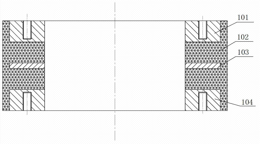
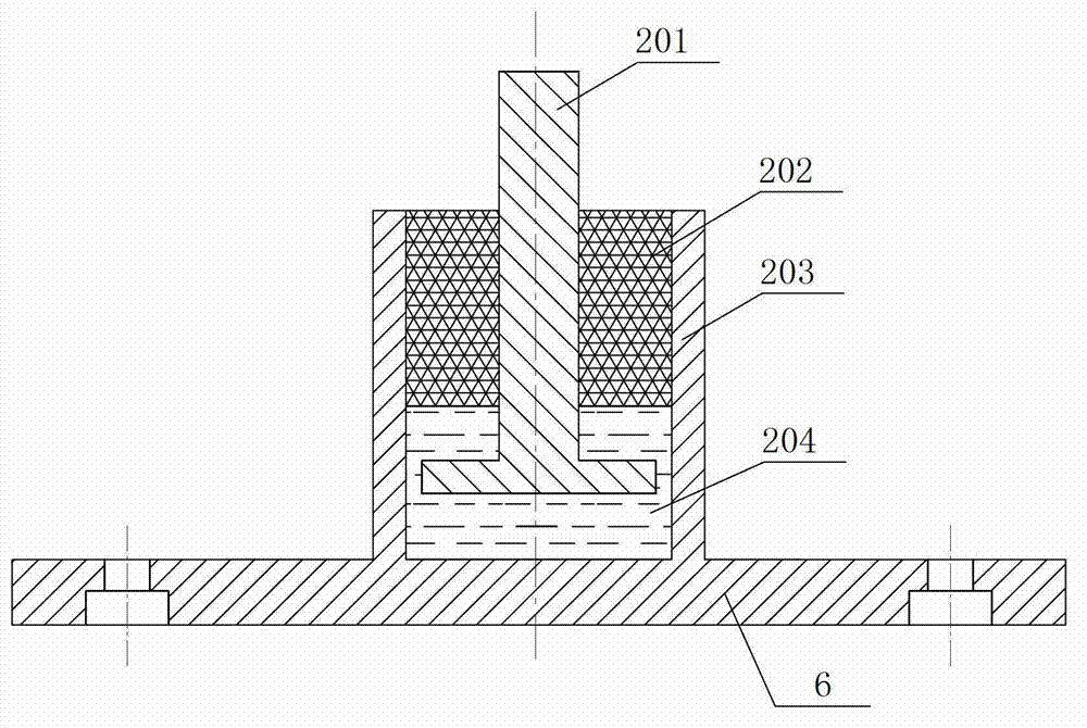
[0037] The vibration isolation mechanism includes a thick rubber support 1, a steel spring support 4 and a damping limiter 2, wherein the damping limiter 2 is located in the middle, and the damping limiter 2 is composed of a cylinder body 203, a rubber body 202, a connecting rod 2...

Embodiment 2

[0042] Embodiment 2 of a combined vibration isolation device for subways of the present invention is as follows Figure 4 As shown, the difference in Embodiment 1 is that the vibration isolation mechanism in this embodiment is only composed of a thick rubber bearing 1 and a damping limiter 2, and does not contain a steel spring bearing 4. The specific structure is: vibration isolation The mechanism includes a thick rubber bearing 1 and a damping limiter 2, wherein the damping limiter 2 is located in the middle, and the damping limiter 2 is composed of a cylinder 203, a rubber body 202, a connecting rod 201 and a viscous liquid 204, The lower end of the barrel 203 is fixedly mounted on the lower connecting plate 6, the viscous liquid 204 is installed in the barrel, the connecting rod 201 and the rubber body 202 are integrally vulcanized and molded, the rubber body 202 is plugged and pressed into the barrel and the mouth of the barrel is blocked, and the connecting rod 201 The l...

Embodiment 3

[0044] The third example of the embodiment of a combined type vibration isolation device for subway of the present invention Figure 5 As shown, the difference of the second embodiment is that the coupling rod 201 in this embodiment is a straight rod, and there is no viscous liquid 204 in the damping limiter 2 .


PUM


Abstract

The invention discloses a combined vibration isolation mounting for subways. The combined vibration isolation mounting comprises an upper connecting plate and a lower connecting plate, wherein the upper connecting plate is located at the upper part, and the lower connecting plate is located at the lower part. The vibration isolation mounting also comprises a vibration isolation mechanism located between the upper connecting plate and the lower connecting plate. The vibration isolation mechanism is respectively and mutually connected with the upper connecting plate and the lower connecting plate to form an integral structure. The vibration isolation mechanism can be used for realizing a function of isolating subway vibrations. According to the combined vibration isolation mounting disclosed by the invention, vertical stiffness, horizontal stiffness and vertical damping can be adjusted. The function of isolating the subway vibrations is realized by the vibration isolation mechanism. The vibration isolation mounting can be applied to a subway floating slab system.

Description

technical field [0001] The invention relates to the technical field of vibration and noise control, in particular to the vibration control of rail transit, in particular to a combined vibration isolation device for subways. Background technique [0002] Urban rail transit has increasingly become an important means to solve urban traffic. When the subway train moves, the stress generated by the contact surface between the wheel and the rail also moves, and the stress distribution in motion is transmitted to the surrounding contact surface, forming a basic motion stress field, which induces secondary vibrations of nearby underground structures and buildings and noise. Vibration tests show that vibration has a great impact on the safety of buildings along the line, the normal use of laboratories and the lives of residents living around the subway. [0003] At present, the subway vibration isolation bearings mainly include steel spring vibration isolation bearings and rubber v...

Claims


Application Information

Patent Timeline
IPC IPC(8): F16F13/14
Inventor 魏久顺王豫
Owner FOSHAN BAJ ISO TECH
Why Eureka
Try Eureka