Eureka AIR delivers breakthrough ideas for toughest innovation challenges, trusted by R&D personnel around the world.

Backlight module and display device

A technology of backlight module and light guide plate, applied in the direction of light guide, optics, optical components, etc., can solve the problems of light guide plate shaking, light source damage, poor reliability of backlight module, etc.

Pending Publication Date: 2019-08-23
XIAMEN TIANMA MICRO ELECTRONICS
View PDF17 Cites 10 Cited by
  • Summary
  • Abstract
  • Description
  • Claims
  • Application Information

AI Technical Summary

Problems solved by technology

In the prior art, when the display device is subjected to a drop test or is dropped during use, it is easy to cause the light guide plate to shake in the light guide plate accommodating space. Tearing the circuit board of the light strip, resulting in damage to the light source and poor reliability of the backlight module

Method used


Image

  • Backlight module and display device
  • Backlight module and display device
  • Backlight module and display device

Examples


Embodiment Construction

[0051] In order to reduce the probability of tearing of the light bar of the backlight module, improve the reliability of the backlight module, and improve the display effect of the display device, an embodiment of the present invention provides a backlight module and a display device. In order to make the purpose, technical solution and advantages of the present invention clearer, the following examples are given to further describe the present invention in detail.

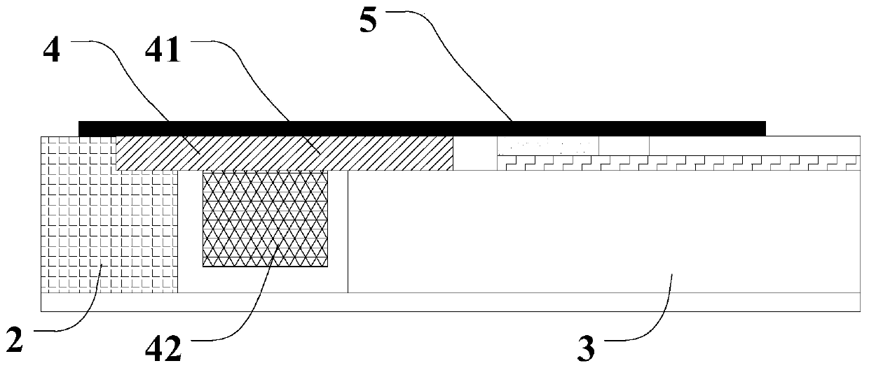
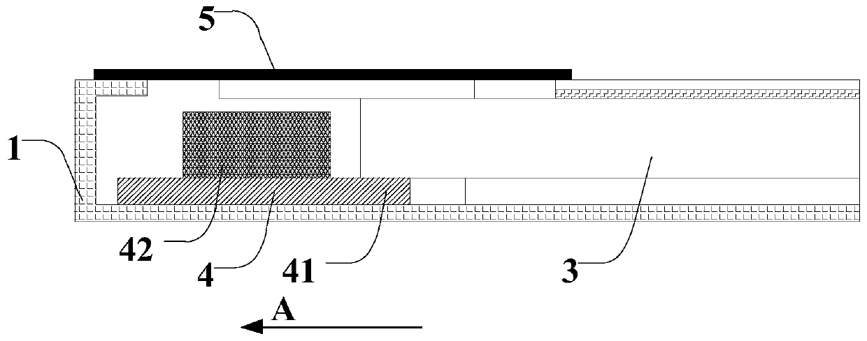
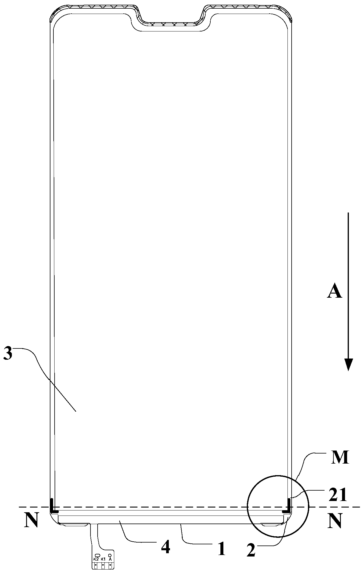
[0052] Such as Figure 1 to Figure 2 As shown, among them, figure 1 It is a schematic diagram of a partial cross-sectional structure of a backlight module according to an embodiment of the prior art; figure 2 It is a schematic diagram of a partial cross-sectional structure of a backlight module according to another embodiment of the prior art. The backlight module can be divided into positive group type and reverse group type according to the installation structure of the light bar 4 . The backlight module ca...


PUM


Abstract

The invention discloses a backlight module and a display device. The backlight module comprises a bottom plate, a side frame and a light guide plate, wherein the bottom plate and the side frame form an accommodating space, the light guide plate is arranged in the accommodating space and comprises a corner part positioned in a corner area of the light guide plate, and at least one buffer structureis arranged between the corner part and the side frame. The buffer structure can reduce the relative displacement generated between the light guide plate and a metal frame when the light guide plate is impacted, thereby reducing the impact force of the light guide plate on a light bar and the force of the light guide plate driving the light bar circuit board bonded on the light guide plate to move, reducing the shearing force to which the lamp strip circuit board is subjected, and reducing the risk of tearing of the light bar. Therefore, the backlight module and the display device can improvethe reliability of the backlight module and the display effect of the display device.

Description

technical field [0001] The invention relates to the field of display technology, in particular to a backlight module and a display device. Background technique [0002] A liquid crystal display device is a flat panel display device. Its working principle is to use the liquid crystal material to modulate light under the action of an electric field to produce various light and dark changes to form images. Since the liquid crystal material itself does not emit light, all liquid crystal display devices require a special backlight module. [0003] The backlight module is one of the key components of the liquid crystal display device. The main function of the backlight module is to provide uniform and high-brightness backlight for the liquid crystal display panel. The basic principle of the backlight module is to convert the commonly used point or line illuminants into surface illuminants with high brightness and uniform gray scale through effective light mechanism, so that the l...

Claims


Application Information

Patent Timeline
IPC IPC(8): G02F1/13357G02B6/00
CPCG02F1/133615G02B6/0066
Inventor 杜欣航王君荣
Owner XIAMEN TIANMA MICRO ELECTRONICS
Why Eureka
Eureka Blog
Learn More