Eureka AIR delivers breakthrough ideas for toughest innovation challenges, trusted by R&D personnel around the world.

Shallow buried steel column base and construction method thereof

A shallow-buried steel column technology, applied in infrastructure engineering, construction, etc., can solve the unreasonable design method of outsourced steel column feet, elongated or pulled out anchor bolts, and damage to welded parts of steel column end plates, etc. problems, to achieve the effect of convenient processing, production and construction, convenient construction, and improved seismic performance

Inactive Publication Date: 2013-03-13
TSINGHUA UNIV +1
View PDF4 Cites 5 Cited by
  • Summary
  • Abstract
  • Description
  • Claims
  • Application Information

AI Technical Summary

Problems solved by technology

Exposed column feet are generally severely damaged. Some anchor bolts are broken, some end plates are pulled off at the edge of the anchor bolts, and some foundation anchor bolts are not broken but are often stretched and pulled out. The end plate of the hinged column base and the column member adopt fillet welds, and there are many cases of partial weld fractures, and the foundation concrete is crushed in many cases, and the observed deformation of the end plate of the column base is rare.
For the outsourcing column foot, when the cross-sectional size of the steel column is not enough or the height of the outsourcing concrete or the thickness of the concrete is not enough, the outsourcing concrete cracks and peels off, some steel column end plate welding parts are damaged, and the anchor bolts are elongated or pulled out The situation exists, which shows that the design method of the outer-wrapped steel column foot in the original design specification is unreasonable and not safe enough

Method used


Image

  • Shallow buried steel column base and construction method thereof
  • Shallow buried steel column base and construction method thereof
  • Shallow buried steel column base and construction method thereof

Examples


Embodiment Construction

[0034] The following describes the implementation of the present invention in detail with reference to the drawings and embodiments.

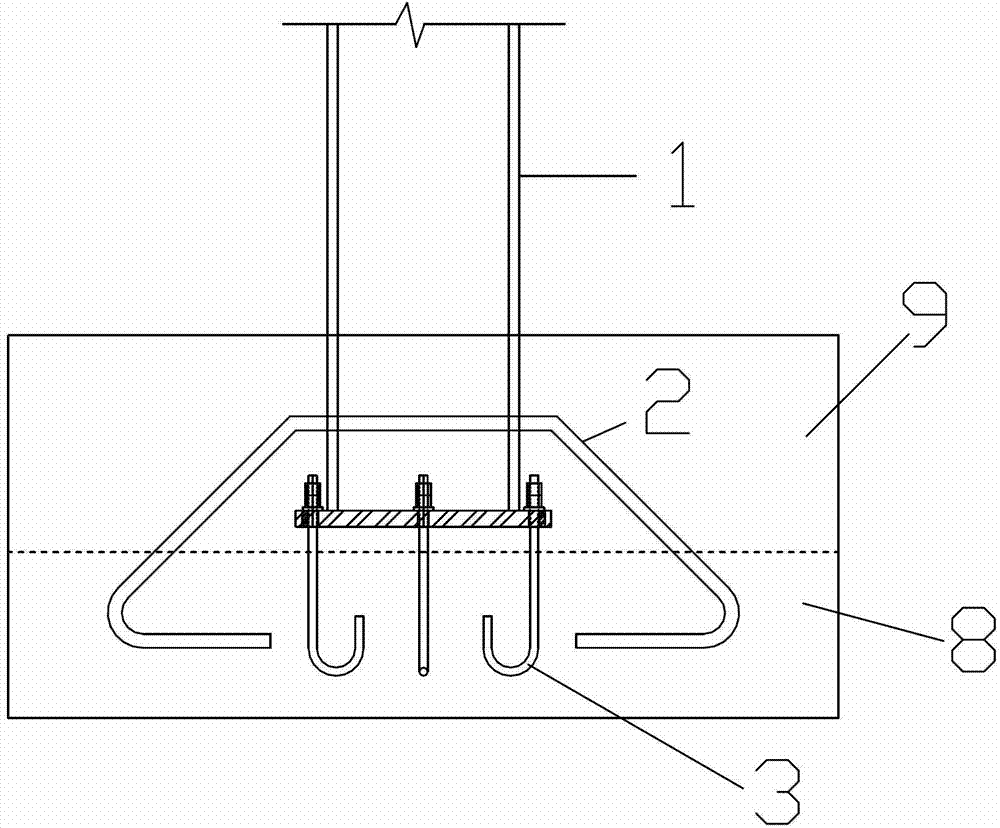
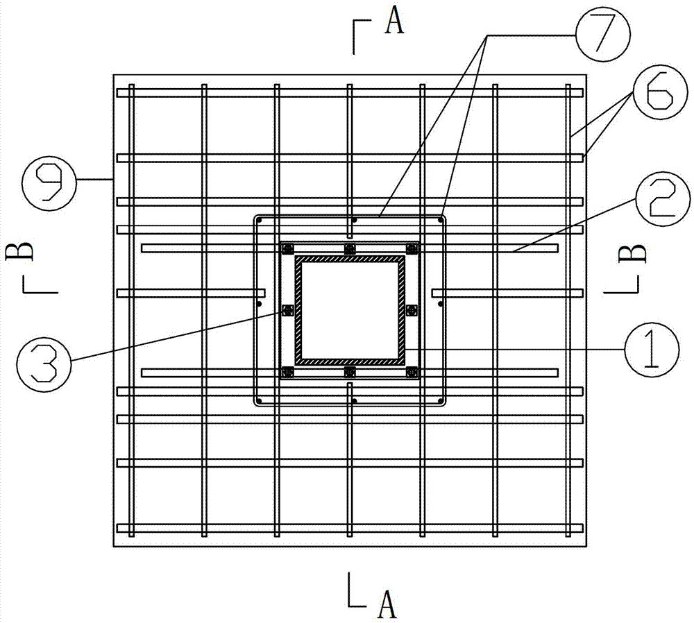
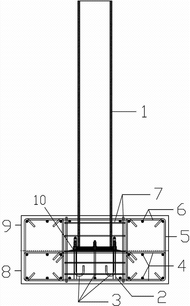
[0035] Such as figure 1 As shown, a shallow-buried steel column foot includes a steel column 1 with an end plate at the bottom, an end plate fixing anchor 3 of the steel column 1, and the other end of the anchor 3 fixed in the bottom plate or foundation beam concrete 8. The bottom of the column 1 is buried in the shallow layer of concrete 9 above the bottom plate or foundation beam concrete 8, where the steel column 1 can have an open section (such as H-shaped or cross-shaped, etc.) or a closed section (such as round, square) Or rectangular, etc.). When the closed section is selected, the concrete is poured into the bottom section of the steel column, the height of the concrete is not less than 1.5 times the thickness of the shallow buried layer outside the pipe, and the strength grade is C30~C40. The thickness of the shallow buried layer concret...


PUM


Abstract

The invention provides a shallow buried steel column base which comprises a steel column, wherein the bottom of the steel column is provided with an end plate; the end plate of the steel column is fixed by virtue of an anchor bolt; the other end of the anchor bolt is fixed in a bottom plate or base beam concrete; and the bottom of the steel column is buried in shallow buried layer concrete above the bottom plate or the base beam concrete. The shallow buried steel column base is of a shear-resistant structure due to the shallow buried layer reinforced concrete, so that the requirement for arrangement of a lower shear-resistant key on the end plate of the steel column is eliminated; and the anchor bolt is not needed to be shear-resistant, so that the difficulty in anchor bolt quantity and arrangement brought by the condition that the anchor bolt participates in shear resistance can be relieved or eliminated, and the shear stiffness and shear bearing capability of the steel column base are effectively improved. The shear-resistant design of the steel column base is simplified, the construction is convenient, and the seismic performance of the steel column base is improved. The invention further provides a construction method of the shallow buried steel column base.

Description

Technical field [0001] The invention belongs to the technical field of steel structures, and particularly relates to a shallow buried steel column foot and a construction method. Background technique [0002] Steel structure has a series of advantages such as high strength, light weight, good seismic performance, fast construction speed, low foundation cost, small occupied area, high degree of industrialization, and beautiful appearance. Compared with concrete structure, it is environmentally friendly and reusable. It is easy to industrialize, and steel structures are widely used in housing construction in developed countries. Building steel structure can be roughly divided into ordinary steel structure and light steel structure. [0003] In the building steel structure, the function of the steel column foot is to transmit the axial force, bending moment and shear force at the lower end of the steel column to the foundation, so that the upper structure and the foundation are effec...

Claims


Application Information

Patent Timeline
IPC IPC(8): E02D27/42
Inventor 赵作周郁银全申林梁志远任玉珊
Owner TSINGHUA UNIV
Why Eureka
Eureka Blog
Learn More