Antenna device and wireless communication device
An antenna device and antenna element technology, which is applied to antenna grounding devices, antennas, devices that make antennas work in different frequency bands at the same time, etc., can solve the problems of inappropriate antenna devices, increase or decrease in the setting area of antenna devices, etc., and achieve simple The effect of forming and reducing electromagnetic coupling
- Summary
- Abstract
- Description
- Claims
- Application Information
AI Technical Summary
Problems solved by technology
Method used
Image
Examples
no. 1 Embodiment approach
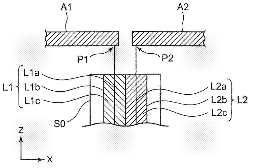
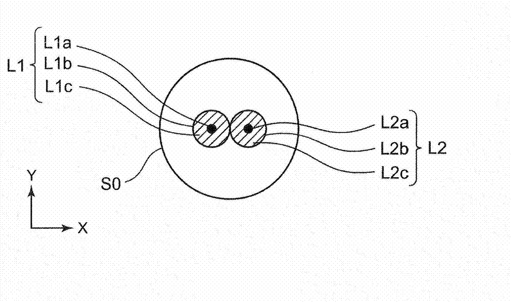
[0091] figure 1 It is a perspective view showing a schematic configuration of the antenna device according to the first embodiment of the present invention. figure 2 is true figure 1 The cross-sectional view showing the vicinity of the feeding points P1 and P2 of the antenna device is a cross-sectional view in a plane parallel to the XZ plane passing through the feeding points P1 and P2 and the feeding lines L1 and L2. image 3 yes figure 1 The cross-sectional view of the antenna device is a cross-sectional view in a plane parallel to the XY plane passing through the sleeve element S0.
[0092] The antenna device of this embodiment includes: two antenna elements A1, A2; two power supply lines L1, L2 respectively having a signal line and a ground conductor; a signal line provided on one end of the antenna element A1 and connected to the power supply line L1 a feeding point P1 electrically connected; and a feeding point P2 provided on one end of the antenna element A2 and el...
no. 2 Embodiment approach
[0111] Figure 15 It is a perspective view showing a schematic configuration of an antenna device according to a second embodiment of the present invention. Sleeve elements are not limited to figure 1 The cylindrical conductor shown by etc. can also be at least one linear conductor. Even with the antenna device of this embodiment, compared with the prior art, it is possible to have a simpler configuration, reduce the electromagnetic coupling between the antenna elements A1 and A2, and enable simultaneous reception and transmission with each antenna element A1 and A2 at a lower mutual value. Correlation of multiple wireless signals. Such as Figure 15 As shown, by using the sleeve elements S1, S2 of the linear conductor, in particular, the following additional effects can be obtained: figure 1 Compared with the sleeve element S0, the volume and weight of the sleeve element S0 can be reduced, the weight of the antenna device can be reduced, and the antenna device can be manu...
no. 3 Embodiment approach
[0115] Figure 17 It is a perspective view showing a schematic configuration of an antenna device according to a third embodiment of the present invention. The antenna device of the present embodiment is characterized in that the antenna elements A1 and A2, the sleeve elements S1 and S2, and the feeder line are formed of conductor patterns on a dielectric substrate.
[0116] The antenna device of this embodiment includes: a ground conductor G0 formed between stacked dielectric substrates D1 and D2; a signal line L1a formed on the upper surface (+Z side surface) of the dielectric substrate D1; The signal line L2a formed on the lower surface (the -Z side surface) of the substrate D2, the ground conductor G0 and the signal line L1a constitute the first power supply line as a microstrip line, and the ground conductor G0 and the signal line L2a constitute a microstrip line. The second power supply line of the line. The antenna device further includes: an antenna element A1 formed...
PUM
 Abstract
Description
Claims
Application Information
 - R&D
- Intellectual Property
- Life Sciences
- Materials
- Tech Scout
- Unparalleled Data Quality
- Higher Quality Content
- 60% Fewer Hallucinations
Browse by: Latest US Patents, China's latest patents, Technical Efficacy Thesaurus, Application Domain, Technology Topic, Popular Technical Reports.
© 2025 PatSnap. All rights reserved.Legal|Privacy policy|Modern Slavery Act Transparency Statement|Sitemap|About US| Contact US: help@patsnap.com


