Penetration distance-composited alcohol spraying method and device
A technology of nozzles and mounting holes, which is applied in the field of alcohol spraying methods and devices with combined penetration distances, can solve the problems of affecting the utilization rate of methanol fuel, reducing the service life of alcohol sprayers, and not being able to atomize well, so as to alleviate the thermal load. Equilibrium phenomenon, promoting the evaporation of methanol liquid film, and improving the effect of fuel atomization
- Summary
- Abstract
- Description
- Claims
- Application Information
AI Technical Summary
Problems solved by technology
Method used
Image
Examples
Embodiment 1
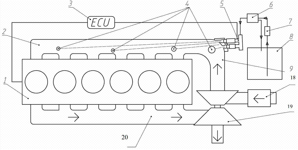
[0047] Combined penetrating alcohol spray device, including:
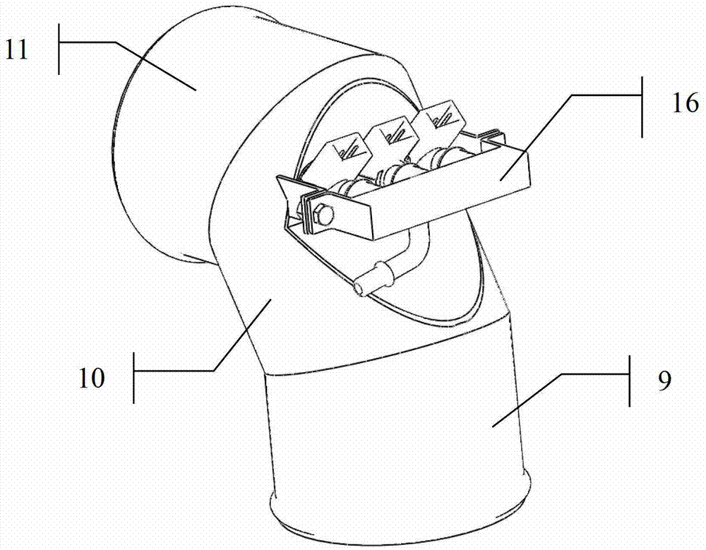
[0048] The intake manifold extension pipe 11 is coaxial with the intake manifold; the intake pipe extension pipe 9 intersects the intake manifold extension pipe 9 and the intake manifold extension pipe 11 at right angles; the connecting elbow 10 connects the intake pipe extension Pipe 9 and intake manifold extension pipe 11; the plane formed between the intake manifold extension pipe 9, the connecting elbow 10, and the centerline of the intake pipe extension pipe 11 is defined as the first plane;
[0049] The first baffle 12 is perpendicular to the centerline of the intake manifold extension pipe and is connected to the outer peripheral surface of the elbow by welding; the second baffle 13 is perpendicular to the first plane; the first baffle 12 and the second baffle 13 The angle between them is 120 degrees;
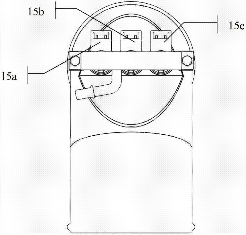
[0050] control Figure 5 , 6 , three nozzle installation holes 14a, 14b, 14c installed vertically on th...
Embodiment 2
[0054] control Figure 8-12, the difference between this embodiment and the embodiment is that the intake manifold extension pipe 11, the connecting elbow 10 and the intake pipe extension pipe are integrally formed, there is no design of the first baffle plate and the second baffle plate, and the nozzle directly passes through the Drill holes at the connecting elbow for installation. Other parts are identical with embodiment 1.
Embodiment 3
[0056] control Figure 13 , 14 , 15, illustrate the implementation scheme of this embodiment. The difference between this scheme and Embodiment 2 is that this embodiment is mainly designed for the intake manifold and intake pipe structure of engineering machinery; when casting, the boss 22 on which the nozzle is installed is cast in advance, and then the nozzle is cast on it. hole to mount the nozzle holder. Other parts are identical with embodiment 2.
PUM
 Abstract
Description
Claims
Application Information
 - Generate Ideas
- Intellectual Property
- Life Sciences
- Materials
- Tech Scout
- Unparalleled Data Quality
- Higher Quality Content
- 60% Fewer Hallucinations
Browse by: Latest US Patents, China's latest patents, Technical Efficacy Thesaurus, Application Domain, Technology Topic, Popular Technical Reports.
© 2025 PatSnap. All rights reserved.Legal|Privacy policy|Modern Slavery Act Transparency Statement|Sitemap|About US| Contact US: help@patsnap.com


