Numerical control equipment

A technology of numerical control equipment and wizards, which is applied in metal processing equipment, large fixed members, driving devices, etc., can solve the problems of poor spindle stability, cannot move too fast, and inaccurate positioning, and achieves good rigidity and consistent processing benchmarks. , Good load-bearing effect

Inactive Publication Date: 2013-02-27
杨东佐
View PDF2 Cites 6 Cited by
  • Summary
  • Abstract
  • Description
  • Claims
  • Application Information

AI Technical Summary

Problems solved by technology

In the moving column type CNC machining center of this invention, since the longitudinal column on which the main shaft is installed is only supported on one side, the main shaft has poor stability, inaccurate positioning, poor movement and too fast movement during movement.

Method used


Image

  • Numerical control equipment
  • Numerical control equipment
  • Numerical control equipment

Examples


Embodiment 1

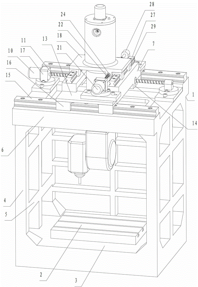
[0021] Such as figure 1 , figure 2 As shown, a numerical control device includes a main body frame 1 and a workbench 2 integrally formed. The main body frame 1 includes a square base 3, which is integrally formed with the base 3 and is arranged at the four corners of the base 3 and the main support columns 4 respectively arranged at the middle positions of the left side, the right side and the rear side of the base, connecting the main support columns 4 Between horizontal connecting column 5. The main support frame 6 arranged on the main support column 4 is integrally formed with the main support column 4 . The main support frame 6 is a square closed-loop structure with an opening facing the vertical direction.

[0022] It also includes the X-direction sliding seat 7. Between the main support frame 6 and the X-direction sliding seat 7, there are mutually matched X forward guide rails and X backward guide rails. The X slide seat 7 can slide back and forth along the X forw...

Embodiment 2

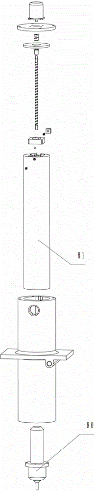
[0038] Such as image 3 As shown, the difference from Embodiment 1 is that the tool holder 80 of the main processing head is directly installed on the Z guide rod 81 .


PUM


Abstract

The invention provides numerical control equipment, wherein a main supporting frame is in a closed loop structure of which the opening faces the vertical direction; an X forward guide rail and an X backward guide rail which are matched with each other are arranged between the main supporting frame and an X-direction sliding seat; a Z-direction guide rod is a round guide rod; the Z-direction guide rod only can be installed together with a Y-direction sliding seat in an up-and-down movement way; a rotation stopping structure for preventing the Z-direction guide rod from rotating along the horizontal direction of the axis of the guide rod is also arranged; the rotation stopping structure comprises a third rotation stopping block, a fourth rotation stopping block, a third spring and a limit mechanism; an accommodation groove is formed in the top part of the Z-direction guide rod; the limit mechanism limits the third rotation stopping block and the fourth rotation stopping block to move in the setting range of the accommodation groove; a rotation stopping groove is formed in a guide hole matched with the Z-direction guide rod; the third spring is installed between the third rotation stopping block and the fourth rotation stopping block; and the third rotation stopping block protrudes from the outer periphery of the Z-direction guide rod and is matched with the rotation stopping groove. The numerical control equipment has the advantages that when a main processing head moves up and down, the stability is good and the imbalance torsion is not easy to generate.

Description

Background technique [0001] Existing numerical control equipment, one is workbench movement. For example, in the invention patent with the application number of 201010284237.9, a CNC gantry vertical compound machine tool is disclosed, including a base, a workbench, and a column. The column is movably connected by a column guide rail or fixedly connected with a composite beam through a fastener. The composite beam passes through the beam. There are more than 2 sliding saddles that are movably connected or fixedly connected by fasteners, and the sliding saddle is movably connected with the main shaft device through the ram guide rail; the base, column, composite beam, and main shaft device are equipped with screw drive devices, and the screw drive The devices are all connected to the electrical numerical control device. [0002] One is the gantry movement. For CNC equipment with this structure, one way is to drive the gantry to move back and forth. The driving mechanism needs ...

Claims


Application Information

Patent Timeline
Patent Type & Authority Applications(China)
IPC IPC(8): B23Q37/00B23Q1/01B23Q1/25B23Q5/02B23Q5/40
Inventor 杨东佐
Owner 杨东佐
Why Eureka
Try Eureka