
Semiconductor device and manufacturing method thereof

一种半导体、器件的技术,应用在半导体器件及其形成领域,能够解决降低空穴迁移率、降低电子迁移率等问题,达到克服集成技术缺陷、集成工艺高度兼容、工艺简单有效的效果

Active Publication Date: 2013-02-13
INST OF MICROELECTRONICS CHINESE ACAD OF SCI
View PDF5 Cites 18 Cited by
  • Summary
  • Abstract
  • Description
  • Claims
  • Application Information

AI Technical Summary

Problems solved by technology

For example, applying compressive stress in the longitudinal direction of current flow will cause compressive strain in the lattice of the channel region, which is beneficial to improve hole mobility, but correspondingly reduces electron mobility.
Applying tensile stress in the longitudinal direction leads to tensile strain of the channel region lattice, which is beneficial to improve electron mobility, but correspondingly reduces hole mobility.

Method used


Image

  • Semiconductor device and manufacturing method thereof
  • Semiconductor device and manufacturing method thereof
  • Semiconductor device and manufacturing method thereof

Examples


Embodiment Construction

[0049] One or more aspects of embodiments of the invention are described below with reference to the drawings, wherein like reference numerals generally refer to like elements throughout. In the following description, for purposes of explanation, numerous specific details are set forth in order to provide a thorough understanding of one or more aspects of the embodiments of the invention. It may be apparent, however, to one skilled in the art that one or more aspects of the embodiments of the invention may be practiced with a lesser degree of these specific details.

[0050] In addition, although a particular feature or aspect of an embodiment is disclosed in terms of only one of some implementations, such feature or aspect may be combined with other implementations that may be desirable and advantageous for any given or particular application. One or more other features or aspects of .

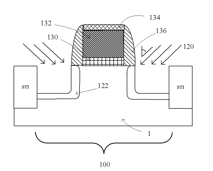
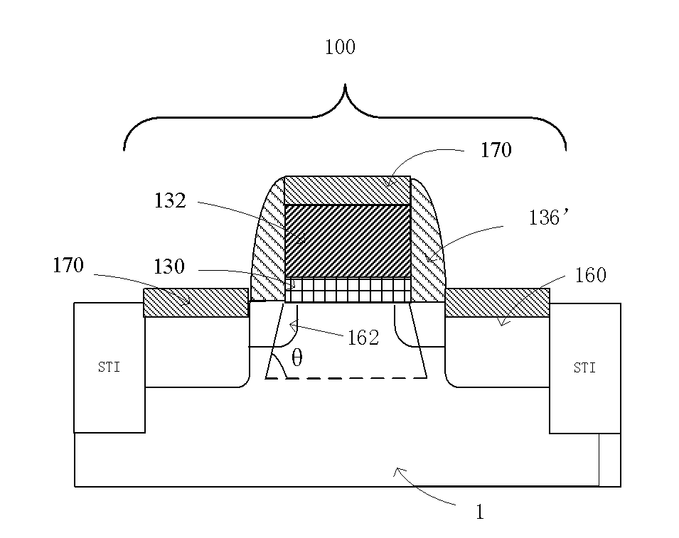
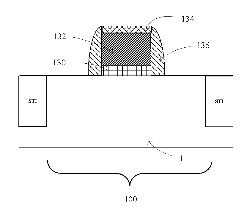
[0051] Referring to FIG. 1 , according to an exemplary manufacturing method of a semicon...


PUM


Abstract

The invention provides a semiconductor device and a manufacturing method thereof. The invention provides a semiconductor device, which comprises a semiconductor substrate of a first semiconductor material and a grid structure positioned on the semiconductor substrate, wherein a crystal lattice dislocation line generating channel stress exists in a channel region at the lower part of the grid structure and forms a certain included angle with a channel.

Description

technical field [0001] The present invention relates to the technical field of semiconductors, in particular to a semiconductor device and a forming method thereof. Background technique [0002] Theoretical and empirical studies have confirmed that when stress is applied to the channel of a transistor, the semiconductor lattice in the channel region is strained, and the carrier mobility of the transistor can be increased or decreased; however, it is also known that the electron and space Caves respond differently to the same type of strain. For example, compressive stress is applied in the longitudinal direction of current flow to cause compressive strain in the channel region, which is beneficial to improve hole mobility, but correspondingly reduces electron mobility. Applying tensile stress in the longitudinal direction leads to tensile strain of the channel region lattice, which is beneficial to improve electron mobility, but correspondingly reduces hole mobility. With ...

Claims


Application Information

Patent Timeline
Patent Type & Authority Applications(China)
IPC IPC(8): H01L29/32H01L27/092H01L21/8238
CPCH01L21/26586H01L29/7843H01L29/7847H01L21/823814H01L21/823807H01L29/7848H01L29/66636H01L21/26506H01L29/24
Inventor 殷华湘徐秋霞陈大鹏
Owner INST OF MICROELECTRONICS CHINESE ACAD OF SCI
Learn More