
Internal gear rack linkage mechanism of gear shaft of engine

A rack, connecting rod and engine technology, applied in the direction of machines/engines, mechanical equipment, etc., can solve the problems of energy consumption and lower overall system efficiency, and achieve the effect of reducing fuel consumption and increasing power

Inactive Publication Date: 2011-04-06
陈亮
View PDF9 Cites 6 Cited by
  • Summary
  • Abstract
  • Description
  • Claims
  • Application Information

AI Technical Summary

Problems solved by technology

In the actual operation process, due to the large swing of the connecting rod (the maximum unilateral swing range can reach about 18 degrees), the vertical component force Psin(a) of the piston reaction force on the cylinder surface, when a is close to the maximum value, due to the piston There is sliding friction between the cylinder and the cylinder, which will cause huge friction force in the direction of piston movement. At this time, it is also the most efficient work stroke section of the crankshaft connecting rod mechanism. The piston must overcome the strong friction force to do work. In addition, the exhaust, intake, Energy is consumed in the compression stroke, as well as in heat loss, which greatly reduces the overall efficiency of the system

Method used


Image

  • Internal gear rack linkage mechanism of gear shaft of engine
  • Internal gear rack linkage mechanism of gear shaft of engine
  • Internal gear rack linkage mechanism of gear shaft of engine

Examples


Embodiment Construction

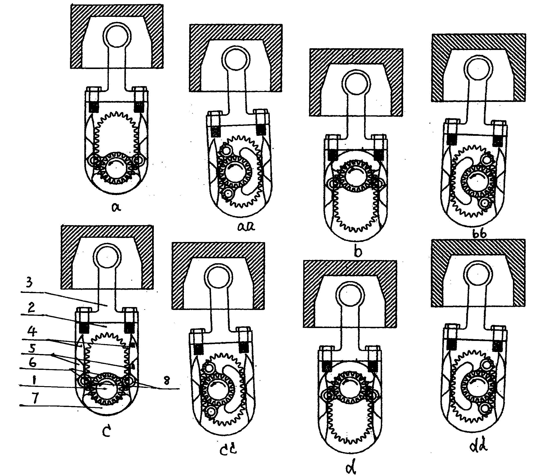
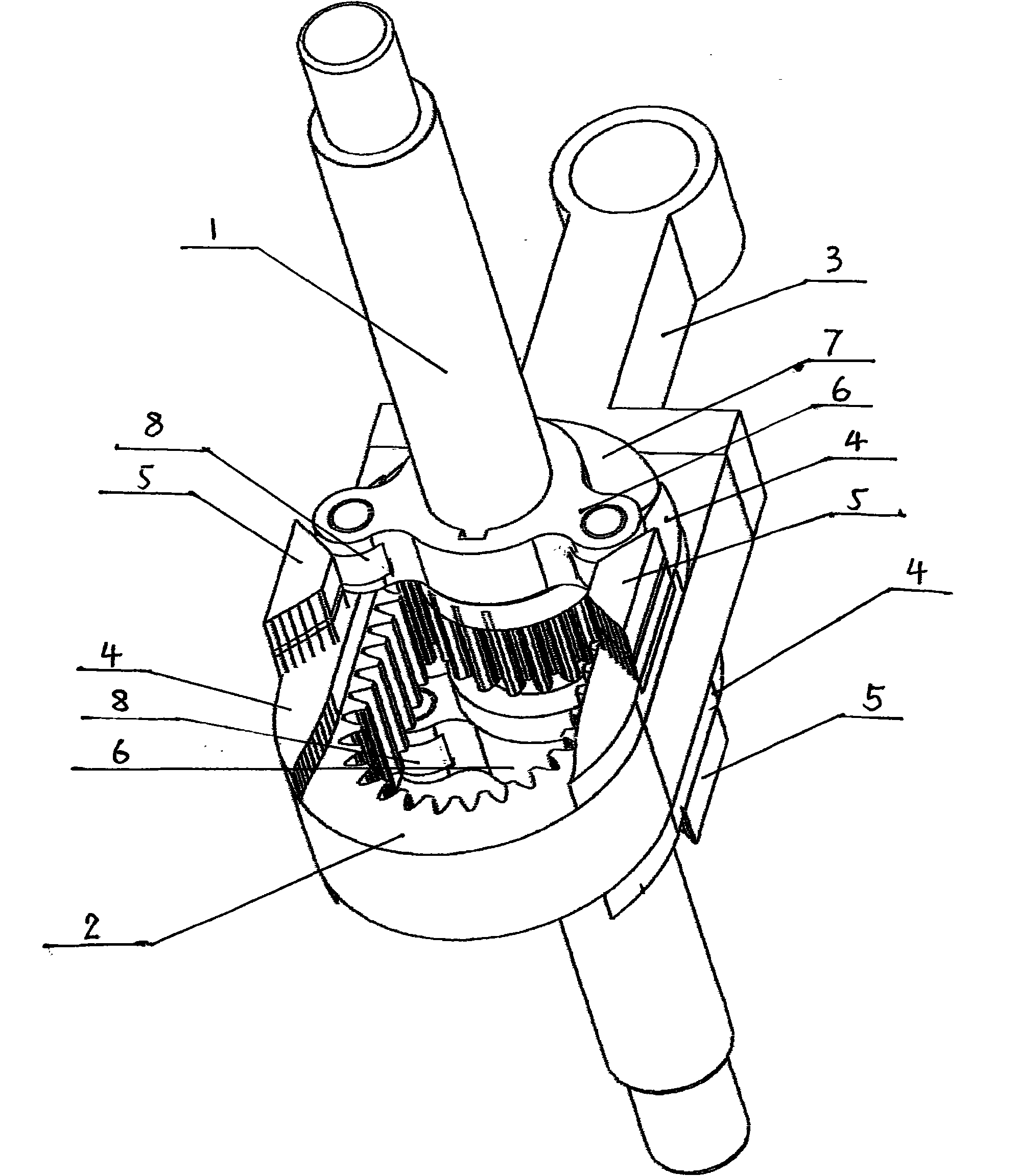
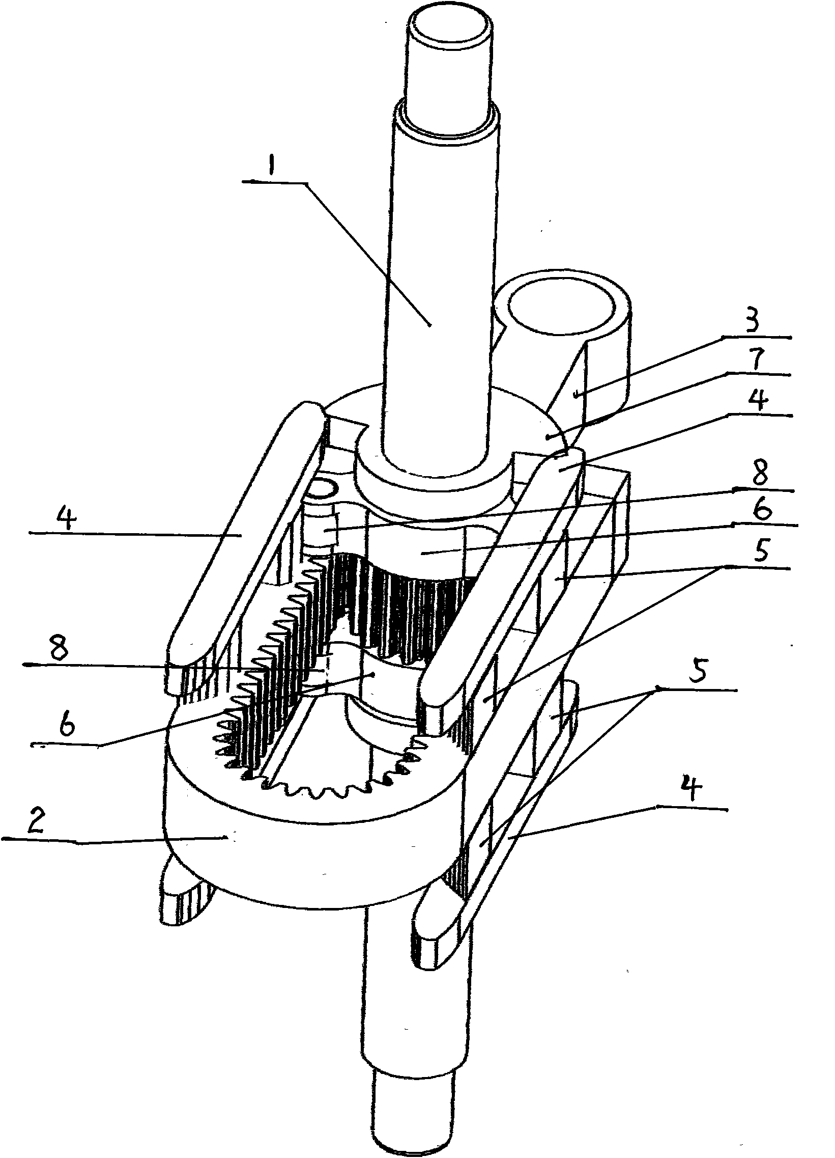
[0012] exist figure 2 In the shown embodiment, the number of external teeth of the external gear shaft (1) is 18, the number of teeth of the internal rack compound internal teeth (2) is 36, and the modulus and pressure angle are the same as those of the external teeth. The number of teeth in the two sections of the rack is 6 teeth, the number of inner teeth is 24, and it passes through the center point of the inner teeth Figure 1A straight line connecting the two root center points divides the inner tooth into two identical parts. The modulus is determined by the engine stroke and torque. The fan angle of fan-shaped sliding guide block (7) is 120 degree, and radius is determined by modulus, and it is fixed on the axle of external gear shaft (1) by key close to the two ends of external gear. Bearing (8) size is determined by modulus. The included angle formed by the axis of the two bearings (8) on the V-shaped rolling guide block (6) and the axis of the external gear shaft...


PUM


Abstract

The invention discloses an internal gear rack linkage mechanism of an external gear shaft of a reciprocating piston-type engine, which is characterized in that a new composite internal gear is formed by two completely identical racks and two identical parts derived from the root of an internal gear having the same modulus, the outer gear shaft is an engine output rotating shaft, the modulus of an external gear on the external gear shaft is the same as that of the composite internal gear, the ratio of the number of teeth of the external gear shaft to the number of teeth of the composite internal gear is 1:2 or 1:3, and the external gear shaft circularly rotates inside the composite internal gear in an engagement manner. In order to achieve the purpose of correct engagement at various positions, two sides of the rack of the composite internal gear as well as the outer gear shaft are equipped with a plurality of guide blocks respectively. The composite internal gear is equipped, via the internal gear, with a linkage fit with a piston pin. The internal gear rack linkage mechanism can take the place of crankshaft linkage mechanism and exert higher conversion efficiency in order to reduce energy consumption dramatically. The internal gear rack linkage mechanism can double the rotating speed of the engine output shaft in the case of the same piston motion frequency of engine.

Description

Technical field [0001] The invention relates to a main motion conversion mechanism of a reciprocating piston engine, which can efficiently convert the expansion pressure of the combustion gas subjected to the piston into the torque output by the engine shaft, and convert the reciprocating motion of the piston into the rotation of the engine shaft Movement and external output power. Background technique [0002] At present, there are two kinds of known piston engines. One is the rotary engine invented by Wankel. It does not have a crankshaft and connecting rod mechanism, because its Mitsubishi cylindrical piston is both a piston and a rotor, and it can act on the piston. The force is transmitted to the external gear on the output shaft of the engine through the internal gear in the piston rotor to make it rotate and output torque externally. Therefore, it has high speed, high power (the rotor does work three times in one revolution), and small vibration. The disadvantage is ...

Claims


Application Information

Patent Timeline
IPC IPC(8): F02B75/32
Inventor 陈亮
Owner 陈亮
Learn More