Double-concave double-reflection type omnidirectional annular view filed imaging lens

An imaging lens and reflective technology, applied in the field of panoramic imaging lenses, can solve the problems of light energy loss, complex optical process, and difficult lens assembly, and achieve the effect of reducing difficulty and improving optical efficiency.

Inactive Publication Date: 2013-02-13
上海臻恒光电系统有限公司
View PDF5 Cites 10 Cited by
  • Summary
  • Abstract
  • Description
  • Claims
  • Application Information

AI Technical Summary

Problems solved by technology

[0005] 1. The materials of the panoramic imaging lens are all refraction materials. After the light is refracted and reflected multiple times in the lens, the optical efficiency is reduced and the light energy is seriously lost;
[0006] 2. When crystal materials are used in the panoramic imaging lens, the optimal design of optical image quality can be realized, but there is a problem that some crystal materials are easy to deliquescence;
[0007] 3. When the binary surface is used in the panoramic imaging lens, the optimal design of optical image quality can be realized, but there is a problem of complex optical technology;
[0008] 4. When the panoramic imaging lens is integrated or multi-piece, it is difficult to manufacture the optical surface;
[0009] 5. When the panoramic imaging lens is integrated or multi-piece, the assembly of the lens is difficult;
[0010] 6. When the panoramic imaging lens is integrated or multi-piece, the selection of lens materials will become complicated, and the optical path will produce large chromatic aberration in front of the relay lens group, making it more difficult for the relay lens group to correct aberrations;
[0011] 7. A panoramic camera composed of a mirror-like panoramic lens has a large optical size, which is not conducive to miniaturization

Method used


Image

  • Double-concave double-reflection type omnidirectional annular view filed imaging lens
  • Double-concave double-reflection type omnidirectional annular view filed imaging lens

Examples


Embodiment Construction

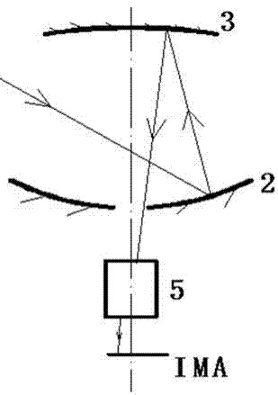
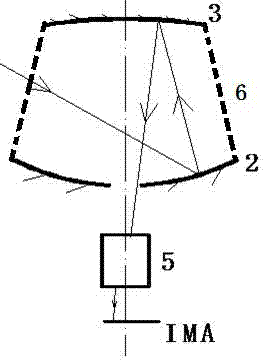
[0027] The reflective surfaces of the first concave reflective mirror surface 2 and the second concave reflective mirror surface 3 are opposite to each other, and they are both rotationally symmetrical about the optical axis (symmetry axis of the optical system); the relay lens group 5 is arranged on the first concave reflective mirror surface. Right behind the reflective mirror 2, that is, facing the middle hole of the first concave reflective mirror 2, and located between the first concave reflective mirror 2 and the focal plane (IMA); the first concave reflective mirror 2 and the second concave reflective mirror 3 are connected to each other through a suitable mechanical support mechanism 6 to form a mirror body.

[0028] The mechanical support mechanism 6 refers to a mechanism that can ensure that the optical interval and optical shading between the first concave reflective mirror surface 2 and the second concave reflective mirror surface 3 meet the specific optical design ...


PUM


Abstract

The invention relates to the technical field of imaging lenses, and particularly relates to a double-concave double-reflection type omnidirectional imaging lens which can be used for realizing the collection and transformation of imaging light rays inside an omnidirectional annular view filed by adopting a concave reflecting mirror surface and a concave reflecting mirror surface. According to the invention, the materials of a reflecting mirror body have wide select range; high optical efficiency is ensured through a reflecting mirror plated with a reflecting film which has high optical efficiency; the concave reflecting mirror surfaces do not generate chromatic aberration in a vacuum or air medium, so that the difficulty of chromatic aberration correction of a relay lens group is reduced; the double concave reflecting mirror surfaces can be respectively selected in the shape of a spherical surface or a non-spherical surface, so that the difficulty of correction of the optical aberrations, namely spherical aberration, comatic aberration, astigmatism, and the like, of the relay lens group is reduced, and good optical image quality is ensured.

Description

technical field [0001] The invention belongs to the technical field of imaging lenses, and in particular relates to a double-concave and double-reflection panoramic imaging lens. Background technique [0002] The optical field of view of the panoramic ring optical lens can be considered to be composed of the optical field of view in two directions, that is, in the Cartesian polar coordinate system, the optical field of view in one direction is located in the XOY plane, that is, the field of view in the azimuth direction The size is 360°, and the size of the optical field of view in the other direction is the difference of the pitch angle. The above two field of view components are represented as rings in the XOY plane, and the value of the rings depends on the lens. Such a lens can image the scene in the 360° annular field of view, so as to achieve a special imaging effect. [0003] There are many forms of panoramic ring lenses, which are divided into refraction and reflec...

Claims


Application Information

Patent Timeline
Patent Type & Authority Applications(China)
IPC IPC(8): G02B13/06G02B13/18G02B17/08G03B37/00
Inventor 李兴隆方中华
Owner 上海臻恒光电系统有限公司
Why Eureka
Try Eureka