Strip plate section form for machining T-section metal strips

A technology of cross-sectional shape and metal strip, applied in the direction of slender components, electrical components, building components, etc., can solve the problems of large local wear, elongation, uneven force on the mold, and improve the yield and service life. , the effect of eliminating cracks

Inactive Publication Date: 2013-02-13
上海格林赛高新材料有限公司
View PDF7 Cites 0 Cited by
  • Summary
  • Abstract
  • Description
  • Claims
  • Application Information

AI Technical Summary

Problems solved by technology

[0008] The rectangular cross-section strip used in method 1 is usually obtained through multiple processes such as ingot hot rolling, cold rolling, and slitting. In the forming of T-shaped section, the processing process becomes complicated due to the difference in processing rate between thick material and thin material
And method 2 is to use the cross-sectional shape similar to the finished product cross-section as the mold shape to continuously cast T-shaped billets or extruded T-shaped billets. The process is short and the project investment is low. In the subsequent forming of the T-shaped section, the subsequent processing becomes simple due to the basically the same processing rate of the thick material and the thin material. Inhomogeneous, internal stress will be generated locally at the junction of thick and thin materials during solidification and shrinkage. When the internal stress is greater than the tensile strength of the material, it will cause small internal cracks that cannot be recognized by the naked eye. In severe cases, obvious cracks will appear. The internal cracks that cannot be recognized by the naked eye will be elongated and appear intermittent long cracks during cold pressure processing, so that the product will be scrapped. At the same time, judging from the shape of the blank ( figure 2 ), due to the excessive size of the step at the junction of thick and thin materials and the asymmetry of the overall shape, the overall force of the mold is uneven and the local wear is too large, which leads to early failure and affects the service life of the mold

Method used


Image

  • Strip plate section form for machining T-section metal strips
  • Strip plate section form for machining T-section metal strips
  • Strip plate section form for machining T-section metal strips

Examples


Embodiment Construction

[0017] The following are the embodiments made according to the technical solution of the present invention in conjunction with the accompanying drawings to further illustrate the present invention.

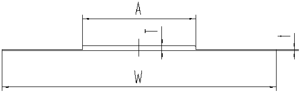
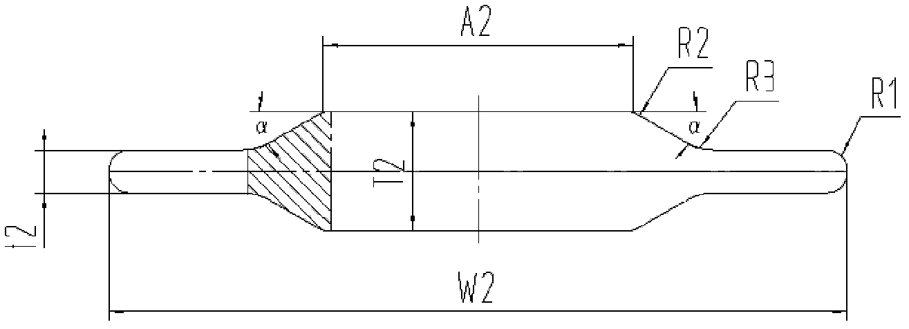
[0018] See figure 1 , the thin material thickness t=0.381mm of the finished product T-shaped strip, the thick material thickness T=1.27mm, A=27mm, W=64mm, the strip blank section shape of the present invention sees image 3 , Thickness t2=4.7mm for thin material, T2=14.5mm for thick material, A2=33mm, α=28°, W2=74mm, R1=1mm, R2=2mm, R3=4mm.

[0019] image 3 The cross-sectional shape of the strip blank shown is a T-shaped strip, and the cross-sectional shape of the strip blank can be a single strip blank cross-sectional shape ( image 3 ) for multiple combination molding ( Figure 4 ), forming a plurality of T-shaped strips is another form of the present invention, and is also within the protection scope of the present invention.


PUM


Abstract

The invention relates to a strip plate section form for machining T-section metal strips. The form is in holohedral symmetry vertically and horizontally; and a transitional area with gradually changed thickness is formed between a thin material t2 and a thick material T2, so that the uniformity is effectively improved when the thick and thin materials are cooled, and local internal stress generated when a thick and thin material interface is solidified and contracted can be reduced or eliminated when the materials are solidified and contracted. Compared with the prior art, the invention has the advantages that cracks of strip plates are reduced or eliminated, the yield is improved, the stress state of a mold is improved, the wear of the mold is reduced and the service life of the mold is prolonged.

Description

technical field [0001] The invention relates to a strip blank sectional shape for processing a T-shaped cross-section metal strip, in particular to a strip blank cross-sectional shape for processing a T-shaped cross-section copper alloy strip for power transistors. Background technique [0002] The cross-section of the T-shaped cross-section copper alloy strip used for power transistors is usually formed by two specifications: thin and thick. The thin material is used as a lead for circuit connection, and the thick material supports the chip and heat dissipation. The common section is shown in figure 1 , is a T-shaped section, the middle is a thick material, which is a trapezoidal protrusion, and the two sides are thin materials of equal size. In order to meet the requirements of high-speed punching dies for frame punching, the dimensional tolerance and surface roughness of the T-shaped section strip Degree, side bending, residual internal stress, etc. have very strict techn...

Claims


Application Information

Patent Timeline
IPC IPC(8): F16S3/00H01L23/495
CPCH01L2224/376H01L2924/00014H01L24/37H01L2224/37599H01L2224/84
Inventor 余波杨惟志
Owner 上海格林赛高新材料有限公司
Why Eureka
Try Eureka