Unfoldable unit of triangular prism and unfoldable support arm consisting of unfoldable units
A triangular prism and folding arm technology, applied in the field of support arms, can solve the problems of large folding volume and low repeated unfolding accuracy, and achieve the effects of high storage rate, enhanced overall rigidity and repeated unfolding accuracy, and light weight
- Summary
- Abstract
- Description
- Claims
- Application Information
AI Technical Summary
Problems solved by technology
Method used
Image
Examples
specific Embodiment approach 1
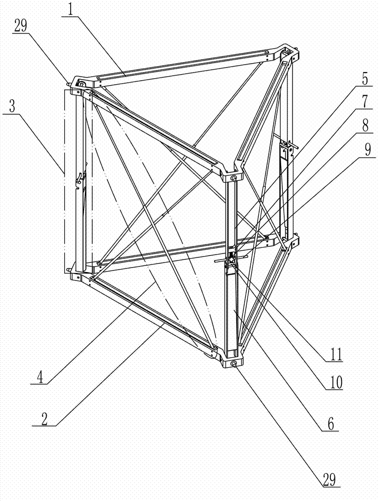
[0010] Specific implementation mode one: combine Figure 1-Figure 5 Describe this embodiment, a triangular prism foldable unit of this embodiment, it includes upper triangular frame 1, lower triangular frame 2, three triangular prism folding arms 3 and three groups of triangular prism cable assemblies 4, upper triangular frame 1 and the lower triangular frame 2 are arranged in parallel from top to bottom, and the positions of the three vertices of the upper triangular frame 1 correspond to the positions of the three vertices of the lower triangular frame 2, and the corresponding positions between the upper triangular frame 1 and the lower triangular frame 2 Each top corner is supported and rotatably connected by a triangular prism folding arm 3 respectively, and the diagonal positions in the rectangular plane formed between the upper triangular frame 1, the lower triangular frame 2 and two adjacent triangular prism folding arms 3 One set of triangular prism cable assembly 4 is...
specific Embodiment approach 2
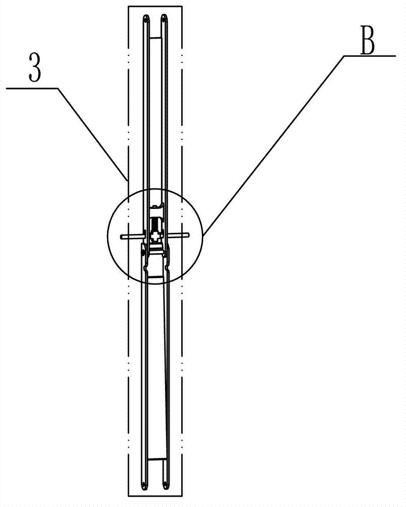
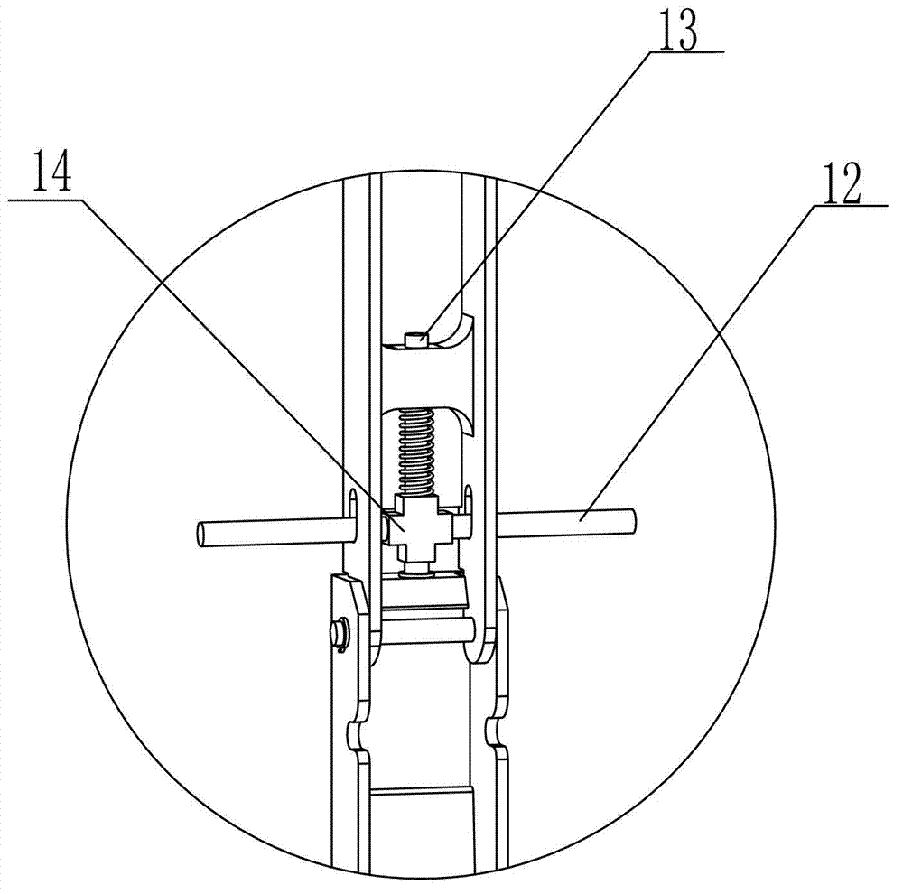
[0012] Specific implementation mode two: combination Figure 1-Figure 3 Describe this embodiment, the triangular prism folding arm 3 of this embodiment includes the unit upper folding arm 5, the unit lower folding arm 6, the unit limit block 7, the unit spring 8, the unit lock frame 9, the unit lock body 10 and the unit taper pin 11. The adjacent ends of the unit upper folding arm 5 and the unit lower folding arm 6 are rotatably connected, the unit limit block 7 is fixed on the lower part of the unit upper folding arm 5, and the unit lock frame 9 is rotatably arranged on the unit upper folding arm 5 and located at the lower end of the unit limit block 7, the unit spring 8 is set on the unit lock frame 9, the unit taper pin 11 is fixed on the lower end of the unit lock frame 9, and the unit lock body 10 is fixed on the upper end of the unit lower folding arm 6 , The unit lock body 10 is provided with a taper hole matching the size of the unit taper pin 11 . In this way, the lo...
specific Embodiment approach 3
[0013] Specific implementation mode three: combination Figure 1-Figure 3 To illustrate this embodiment, the unit lock frame 9 of this embodiment includes a unit horizontal shaft 12, a unit vertical shaft 13 and a unit "ten" connecting block 14, and the unit horizontal rotating shaft 12 is horizontally installed on the unit "ten" connecting block 14 On the top, the unit vertical shaft 13 is vertically installed on the upper end of the unit "ten" connecting block 14, the unit spring 8 is set on the unit vertical shaft 13, and the unit taper pin 11 is fixed on the unit "ten" connecting block 14 the lower end. Such setting is convenient and flexible to use. Other compositions and connections are the same as those in the second embodiment.
PUM
 Abstract
Description
Claims
Application Information
 - R&D
- Intellectual Property
- Life Sciences
- Materials
- Tech Scout
- Unparalleled Data Quality
- Higher Quality Content
- 60% Fewer Hallucinations
Browse by: Latest US Patents, China's latest patents, Technical Efficacy Thesaurus, Application Domain, Technology Topic, Popular Technical Reports.
© 2025 PatSnap. All rights reserved.Legal|Privacy policy|Modern Slavery Act Transparency Statement|Sitemap|About US| Contact US: help@patsnap.com


