
Pneumatic radial tire

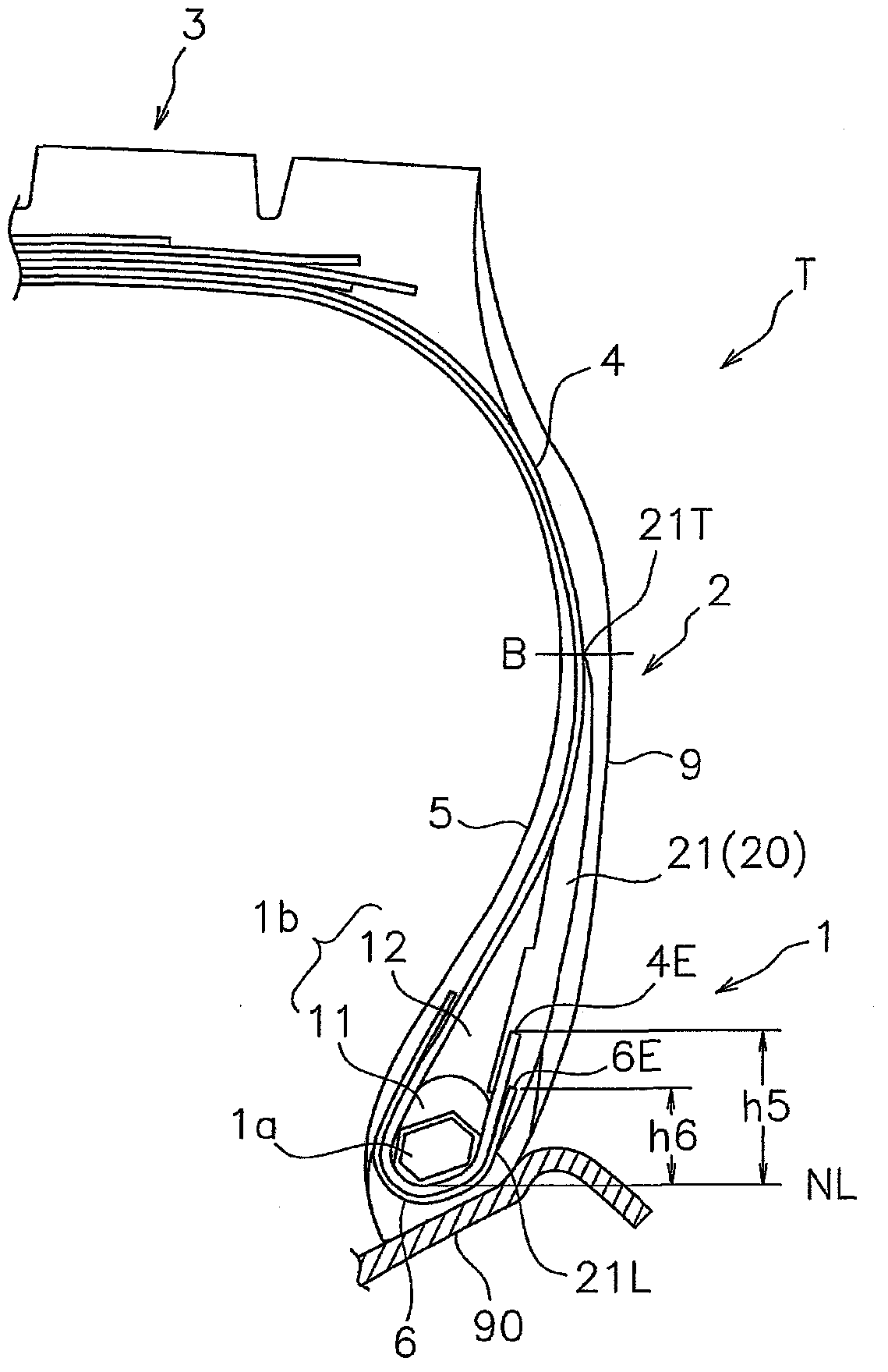
A radial tire and tire technology, applied in tire parts, tire edges, tire sidewalls, etc., can solve problems such as large deformation of the winding end of the ply, and achieve the effect of suppressing failure, improving durability, and suppressing bulging deformation.

Active Publication Date: 2013-02-13
TOYO TIRE & RUBBER CO LTD
View PDF5 Cites 10 Cited by
  • Summary
  • Abstract
  • Description
  • Claims
  • Application Information

AI Technical Summary

Problems solved by technology

If such bulging deformation is repeated with the rolling of the tire, a large deformation occurs at the ply turn-up end 4E or chafer turn-up end 6E that is collapsed toward the outside, and failures starting from these tend to occur.

Method used


Image

  • Pneumatic radial tire
  • Pneumatic radial tire
  • Pneumatic radial tire

Examples


Embodiment

[0073] Hereinafter, a durability test of the bead portion was carried out in order to specifically demonstrate the structure and effect of the present invention. Described below. The size of the tire provided for the test was 11R22.5, and it was mounted on a rim of the size specified by JATMA.

[0074]In the durability test, the tire was run on a roller under the conditions of an internal pressure of 900 kPa and a speed of 40 km / h, and the load was gradually increased from 230% of JATMA normal conditions to evaluate the running distance when failure occurred. Therefore, the longer the travel distance, the better the durability.

[0075] Table 1 shows the bead structures and evaluation results of Comparative Examples 1-3 and Examples 1-4. The bead structures of Comparative Examples 1 and 2 are shown in Image 6 , 7 , in Comparative Example 2, the reinforcing rubber is formed of a rubber material having the same composition ratio as that of the upper filling rubber. The bea...


PUM


Abstract

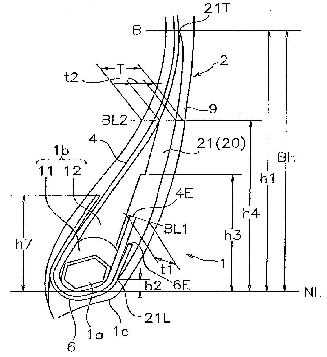
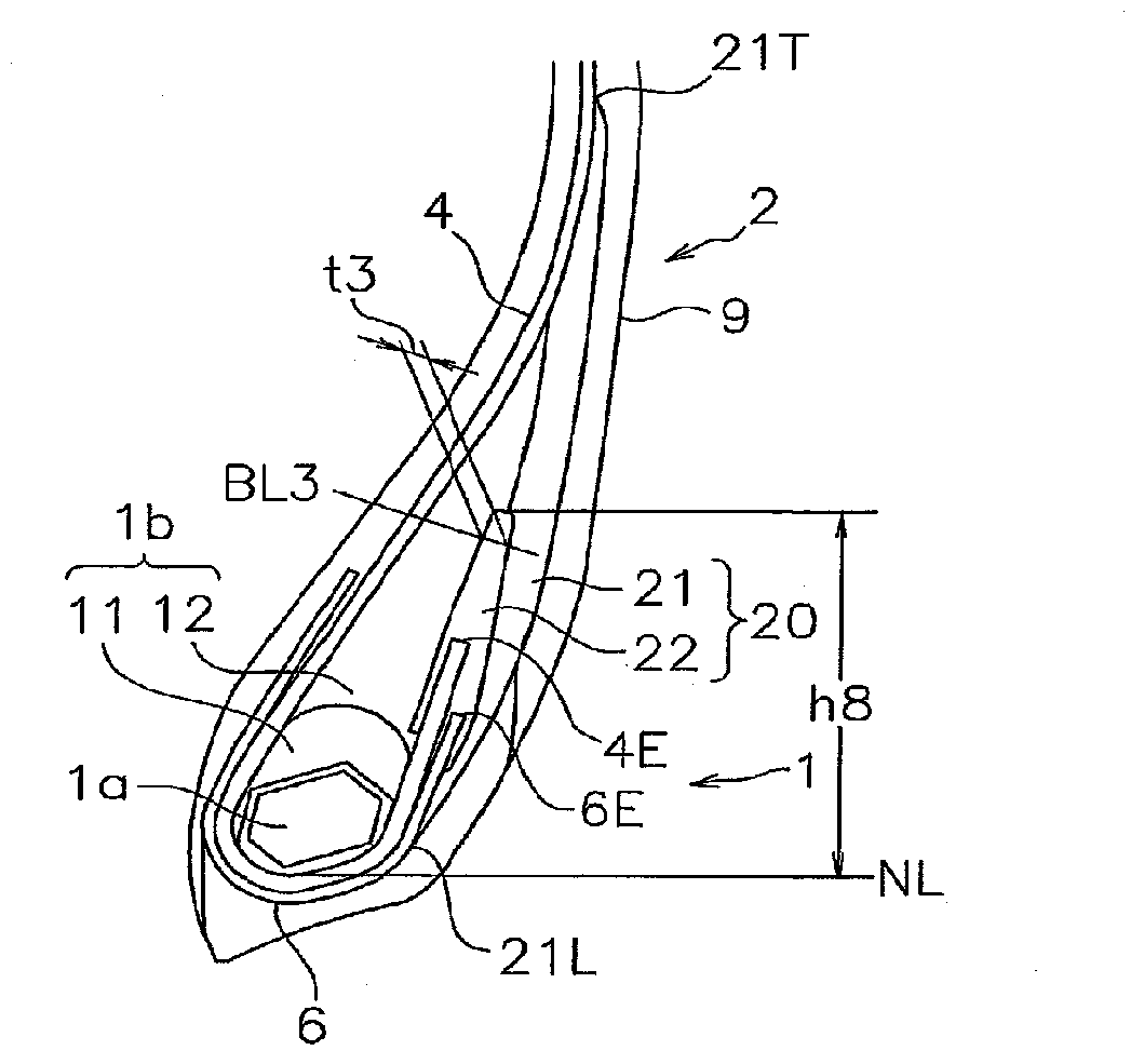
A pneumatic radial tire has a carcass ply wound up around a bead core, a chafer wound up around the bead core to be arranged in an outer side of the carcass ply, and a side wall rubber. A reinforcing rubber is provided between a rubber filler and the side wall rubber to pinch a wind-up end of the carcass ply and a wind-up end of the chafer. The reinforcing rubber has a monolithic layer extending in a tire diametrical direction. An upper end of the monolithic layer is positioned at a height which is 0.9 to 1.1 times a height of a tire maximum width position based on a rim reference line. A lower end of the monolithic layer is positioned in an outer side of the chafer at a height within +-10 mm based on the rim reference line.

Description

technical field [0001] The present invention relates to a high-durability pneumatic radial tire characterized by a structure of a bead portion, and is particularly useful as a heavy-duty pneumatic radial tire. Background technique [0002] In the prior art, particularly in pneumatic radial tires used for heavy vehicles such as industrial vehicles or construction vehicles, there has been concern that delamination, etc. Fault. Therefore, as disclosed in the following Patent Documents 1 and 2, a reinforcing member called a chafer is generally disposed along the carcass. However, even if a chafer is provided, the durability may be lowered due to protruding deformation of the bead portion, so there is room for further improvement. [0003] Figure 8 It is a figure explaining the protrusion deformation of a bead part. When the tire is running, the sidewall portion is largely bent due to internal pressure and load, and the bead portion 1 is deformed outwardly along the rim edge ...

Claims


Application Information

Patent Timeline
Patent Type & Authority Applications(China)
IPC IPC(8): B60C15/00B60C15/06
CPCB60C15/0607B60C15/06B60C15/00B60C2015/0617B60C15/0635B60C13/00B60C2015/061
Inventor 儿玉纪彦
Owner TOYO TIRE & RUBBER CO LTD
Learn More