Electric-resistance-welded steel pipe with excellent torsion fatigue resistance and process for producing same

A technology of electric resistance welded steel pipe and manufacturing method, applied in electric resistance welding equipment, rigid pipes, manufacturing tools, etc., to achieve the effect of reliable fatigue resistance characteristics

Active Publication Date: 2013-01-30
JFE STEEL CORP
View PDF6 Cites 10 Cited by
  • Summary
  • Abstract
  • Description
  • Claims
  • Application Information

AI Technical Summary

Problems solved by technology

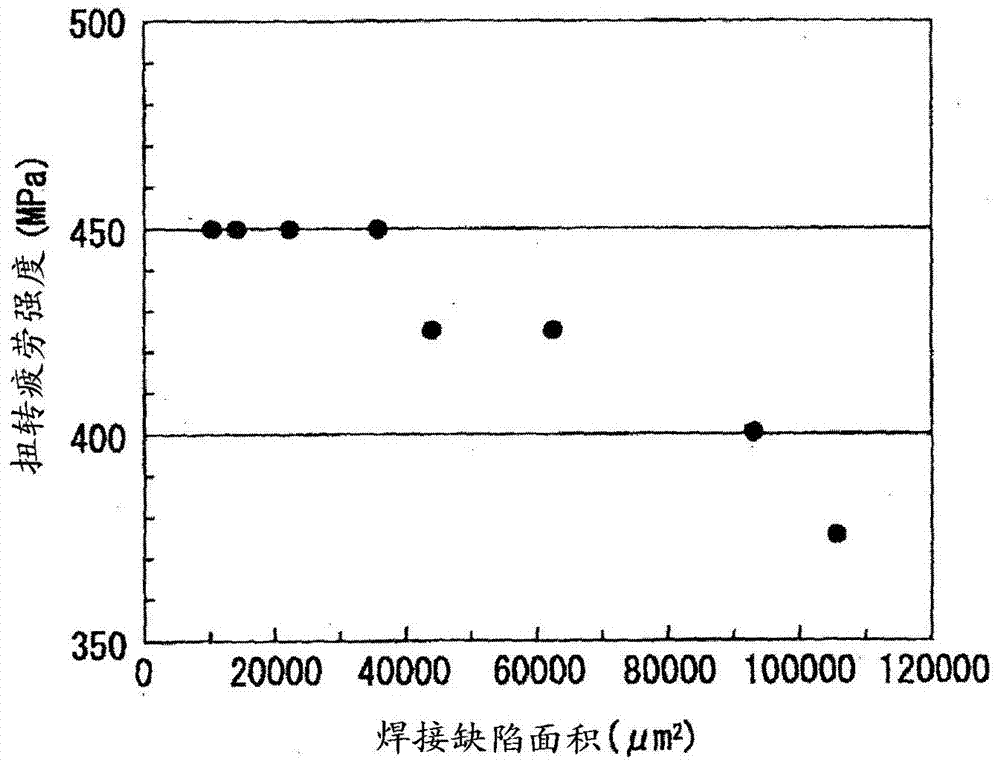
[0008] The inventors have studied defects near the electric resistance welded portion which is a problem when electric resistance welded steel pipe is used for the propeller shaft

Method used


Image

  • Electric-resistance-welded steel pipe with excellent torsion fatigue resistance and process for producing same
  • Electric-resistance-welded steel pipe with excellent torsion fatigue resistance and process for producing same
  • Electric-resistance-welded steel pipe with excellent torsion fatigue resistance and process for producing same

Examples


Embodiment

[0086] A steel strip obtained by hot-rolling a cast steel sheet having the steel composition (mass %) shown in Table 1 was used as a pipe material to manufacture an electric resistance welded steel pipe. At this time, as the electric resistance welding condition, welding heat energy and top The combination of the amount of forging was adjusted according to the following two conditions to manufacture electric resistance welded steel pipes. That is, normal conditions (resistance welding condition A in Table 2) where oxides and inclusions hardly remain and conditions (resistance welding condition B in Table 2) tend to remain.


PUM

PropertyMeasurementUnit
areaaaaaaaaaaa

Abstract

Fatigue properties required of drive shafts cannot be always guaranteed with conventional electric-resistance-welded steel pipes. Disclosed is an electric-resistance-welded steel pipe which comprises a base metal having a composition containing 0.25-0.55% C, 0.01-1.0% Si, 0.2-3.0% Mn, up to 0.1% Al, and 0.0010-0.0100% N, with the remainder comprising Fe and incidental impurities. The steel pipe is characterized in that the area of weld defects which is the area of weld defects projected on the weld formed by electric-resistance welding is less than 40,000 [mu]m2.

Description

technical field [0001] The present invention relates to an electric resistance welded steel pipe excellent in torsion fatigue resistance and a manufacturing method thereof. Background technique [0002] In the automobile industry, in order to achieve both weight saving and stiffness increase, the drive shaft has been hollowed out. For such hollowing, seamless steel pipe (seamless steel pipe) has been used as a material. For example, Patent Document 1 describes a hollow drive shaft (hollow drive shaft), which uses a seamless steel pipe whose steel composition is controlled within a desired range as a material, and has an austenite grain size number after quenching. (austenitic grain size number) is 9 or more excellent cold-workability (cold-workability), hardenability, toughness and torsional fatigue strength and stable fatigue life (fatigue life time). However, the seamless steel pipe has the following problems in its manufacturing method: due to surface decarburization an...

Claims


Application Information

Patent Timeline
Patent Type & Authority Applications(China)
IPC IPC(8): C22C38/00C21D9/08C21D9/28C21D9/50C22C38/06C22C38/58
CPCC22C38/14C21D9/08C22C38/002C22C38/06C21D9/50B23K11/0873C22C38/02C22C38/04B23K9/00C22C38/001F16L9/02C22C38/42
Inventor 荒谷昌利河端良和冈部能知饭塚幸理堀弘道郡司牧男岩崎谦一
Owner JFE STEEL CORP
Why Eureka
Try Eureka