Pneumatic deep groove digging device

A power device, deep groove technology, applied in the direction of earth mover/shovel, construction, etc., can solve the problems of not significantly improving the slag discharge capacity, unable to ensure the smooth progress of construction, unable to achieve the role of assisting slag discharge, etc. Clever, stable work, avoid occupancy effect

Inactive Publication Date: 2015-04-22
启东晟涵医疗科技有限公司
View PDF8 Cites 0 Cited by
  • Summary
  • Abstract
  • Description
  • Claims
  • Application Information

AI Technical Summary

Problems solved by technology

[0004] However, the above-mentioned equipment still has the following problems: in areas with abundant groundwater, the accumulation of water in the foundation pit below the groundwater level will cause the equipment to be flooded, and the excavation capacity of the equipment will be greatly limited. It will be difficult to extract slag by wind
At the same time, the pit wall support is insufficient during the excavation process, and only the spray protection of the foundation pit cannot meet the requirements and it is easy to collapse
In addition, because the air inlet pipe is set inside the slag discharge pipe, it occupies a part of the slag discharge space. On the other hand, because the bell mouth enters from the large mouth, there are more soil slags, which need to be discharged from the small opening. If the soil slag that arrives at the same time Too much will form a blockage, and the slag-discharging device only accelerates the speed of the slag from behind, and it will still weaken with the increase of the distance. Even once the blockage, the airflow cannot pass through, so that the real slag-discharging effect cannot be achieved. ; At the same time, the output of compressed air needs a large-power air compressor to achieve, the slag discharge capacity is not significantly improved, but the energy consumption is significantly increased; Although the moving motor or hydraulic motor provides auxiliary power, if the power is further increased, the size will inevitably increase, which will exceed the required slotting range, and it is difficult to meet the requirements of large power and small volume, and the auxiliary power output by two shafts Poor stability and short service life cannot guarantee the smooth progress of construction

Method used


Image

  • Pneumatic deep groove digging device
  • Pneumatic deep groove digging device
  • Pneumatic deep groove digging device

Examples


Embodiment Construction

[0024] The present invention is further illustrated and explained below in conjunction with the examples.

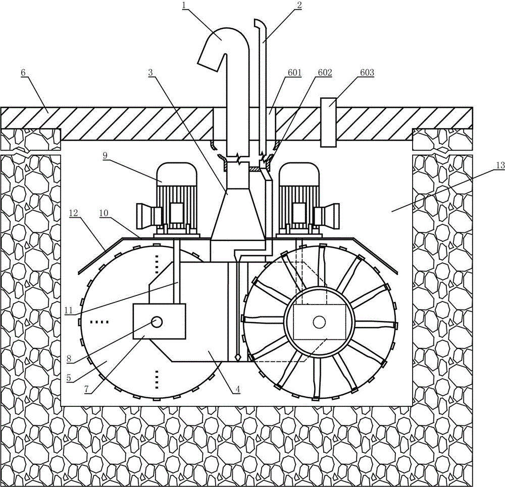
[0025] Pneumatic deep groove excavation device of the present invention, as figure 1 As shown, it includes a conduit 1, a horn-shaped tubular body 3 fixedly connected to the end of the conduit 1 through a small mouth end, and the upper part passes through the side wall of the horn-shaped tubular body 3 and is connected to the air intake pipe on the outside of the horn-shaped tubular body 3 and the conduit 1 2. The sealing cover plate 6 set on the conduit 1 and the intake pipe 2 through the central through hole 601, the fixed frame 4 fixedly connected to the large mouth end of the trumpet-shaped pipe body 3, and the cutting wheel 5 arranged on the fixed frame through bearings; The sealing cover plate 6 generates air pressure inside by sealing the notch of the foundation pit 13, which strengthens the power of slag discharge from the inside; after the upper part of the air ...


PUM


Abstract

The invention relates to a drilling tool for opening a hole and digging a groove, and particularly relates to a pneumatic deep groove digging device which has strong dreg discharging capability, small size and enough power output, can automatically finish water discharging of a foundation pit below an underground water level, and can realize pressure support of a pit wall of the foundation pit in a process of digging the foundation pit. The digging device comprises a guide pipe (1), an air inlet pipe (2), a loudspeaker-shaped pipe body (3), a fixing frame (4) and a cutting wheel (5), wherein the air inlet pipe (2), the loudspeaker-shaped pipe body (3) and the fixing frame (4) are connected to the guide pipe (1); the cutting wheel (5) is arranged on the fixing frame (4) through a bearing; the digging device further comprises a sealing cover plate (6) which is sleeved on the guide pipe (1) and the air inlet pipe (2) through central through holes (601) and the sealing cover plate (6) is arranged at a groove opening of the foundation pit (13) to seal the inner part of the foundation pit (13); the upper part of the air inlet pipe (2) penetrates through the side wall of the loudspeaker-shaped pipe body (3), and is connected at the outer sides of the loudspeaker-shaped pipe body (3) and the guide pipe (1); and a small-opening end of the loudspeaker-shaped pipe body (3) is fixedly connected with the tail end of the guide pipe (1), and a large-opening end of the loudspeaker-shaped pipe body (3) is fixedly connected with the fixing frame (4).

Description

technical field [0001] The invention relates to a drilling tool for opening holes and digging grooves, in particular to a pneumatic deep groove digging device. Background technique [0002] In the prior art, the construction of pile foundations, underground diaphragm walls, waterproof and drainage structures, etc. is usually realized by slotting. The required troughs are for the construction of underground projects on the one hand and to provide the necessary site for underground construction on the other hand. , conditions and space. At present, the excavation construction of the trench is usually completed manually and by an excavator, and there is also a method of excavating by a drilling rig and then trying to connect it, which is generally used in the construction of an underground diaphragm wall. Manpower needs enough space for people to go down into the foundation pit for construction, but the engineering structure actually does not need such a large space, so the co...

Claims


Application Information

Patent Timeline
Patent Type & Authority Patents(China)
IPC IPC(8): E02F5/08E02F5/14
Inventor 牛发启
Owner 启东晟涵医疗科技有限公司
Why Eureka
Try Eureka