
Miniaturized multi-path two-way signal optical fiber transmission component

A technology of optical fiber transmission and two-way signal, which is applied in the direction of optical fiber transmission, etc., can solve the problems that the radar system cannot meet the requirements of small size and multi-functionality, and cannot realize the two-way transmission of multi-channel data, etc., and achieve the effect of strong anti-interference ability and small size

Active Publication Date: 2013-01-16
8TH RES INST OF CETC
View PDF3 Cites 14 Cited by
  • Summary
  • Abstract
  • Description
  • Claims
  • Application Information

AI Technical Summary

Problems solved by technology

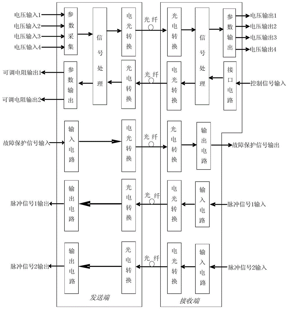
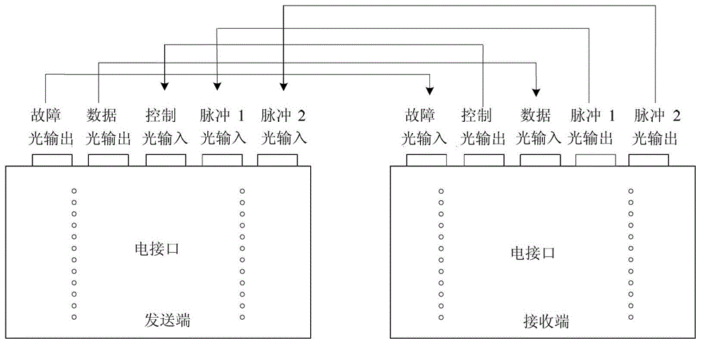
This multi-channel data optical fiber transmission component can realize the transmission of 4 channels of analog voltage signals, 2 channels of pulse signals, and 2 channels of data signals. It has been applied in the high-voltage detection and high-voltage isolation of radar traveling wave tubes. However, the component is as mentioned above. It is impossible to realize the two-way transmission of multi-channel data through an optical fiber, and the large size of the component cannot meet the needs of small volume and multi-function required by the continuous development of radar systems

Method used


Image

  • Miniaturized multi-path two-way signal optical fiber transmission component
  • Miniaturized multi-path two-way signal optical fiber transmission component
  • Miniaturized multi-path two-way signal optical fiber transmission component

Examples


Embodiment Construction

[0030]The specific embodiment of the present invention is described in detail below in conjunction with accompanying drawing:

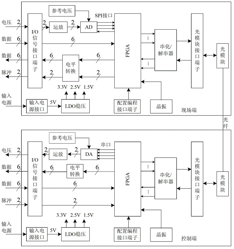
[0031] refer to image 3 As shown, the miniaturized multi-channel bidirectional signal optical fiber transmission assembly of this embodiment includes a field terminal and a control terminal using a multi-chip stacked packaging structure. The field end includes a first FPGA, an analog-to-digital converter, a first level converter, a first optical module, a first I / O signal interface terminal packaged in BGA, and the like. The control terminal includes a second FPGA, a digital-to-analog converter, a second level shifter, a second optical module, and a second I / O signal interface terminal in a BGA package, etc., and the second optical module and the first optical module pass through A transmission optical fiber is connected, wherein:

[0032] In the field end, the first I / O signal interface terminal is used to provide the input interface of 2 voltage ...


PUM


Abstract

The invention discloses a miniaturized multi-path two-way signal optical fiber transmission component. The miniaturized multi-path two-way signal optical fiber transmission component comprises a field end and a control end which have multi-chip stack encapsulation structures; the field end is connected with the control end through a transmission optical fiber; the control end can input a plurality of voltage signals and a plurality of data signals, convert a plurality of voltage signals and a plurality of data signals into a positive emitter coupled logic (PECL) signal and transmit the PECL signal to the control end through an optical module and a transmission optical cable; the control end reduces the received PECL signal into a plurality of voltage signals and a plurality of data signals and outputs a plurality of voltage signals and a plurality of data signals; the control end also can input a plurality of transistor-transistor logic (TTL) pulse signals and a plurality of data signals, convert a plurality of TTL pulse signals and a plurality of data signals into the PECL signal, and transmit the PECL signal to the field end through the optical module and the transmission optical cable; the field end reduces the received PECL signal into a plurality of data signals and a plurality of TTL pulse signals and outputs a plurality of data signals and a plurality of TTL pulse signals, so that a plurality of two-way signals are transmitted by an optical fiber, and the anti-jamming capacity is high; and therefore, the miniaturized multi-path two-way signal optical fiber transmission component is particularly suitable for the data transmission of a modern airborne and ship-borne radar system.

Description

technical field [0001] The invention relates to an optical fiber transmission device of a radar system, in particular to a miniaturized multi-channel bidirectional signal optical fiber transmission assembly. Background technique [0002] With the continuous development of radar technology, while the performance is continuously improved, the radar is developing in the direction of miniaturization. On the other hand, the amount of data that the radar system needs to process and transmit is increasing, and the number of signal channels is also increasing. There are many, including analog signals, data signals, and pulse signals. The types of these signals are different and the transmission rates are different. The requirements of the radar system for these signals are also different. The increase in the number of signal channels makes the radar system larger in size and heavier in weight, which is unacceptable to airborne and shipborne radars. Compared with traditional cable co...

Claims


Application Information

Patent Timeline
Patent Type & Authority Applications(China)
IPC IPC(8): H04B10/25
Inventor 高进杨鹏毅陆兆辉孙磊吴振刚
Owner 8TH RES INST OF CETC
Learn More