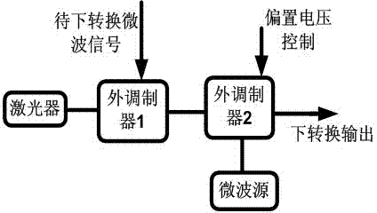
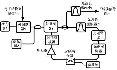
Photon type frequency down-conversion device and method
A frequency down-conversion, electro-optical conversion technology, used in power oscillators, electromagnetic wave transmission systems, electrical components, etc., can solve the problem of effectively suppressing noise and interference at the carrier frequency, reducing the bandwidth of the band-pass filter, and affecting the down-conversion performance, etc. problem, to overcome the limitation of operating frequency, reduce cost and complexity, and avoid serious impact
- Summary
- Abstract
- Description
- Claims
- Application Information
AI Technical Summary
Problems solved by technology
Method used
Image
Examples
specific Embodiment 1
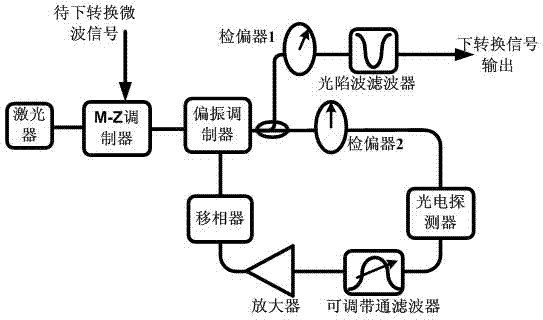
[0030] The laser outputs an optical continuous wave, and the microwave signal to be down-converted at the Mach-Zehnder modulator (the carrier frequency is set to fm ) to the optical carrier to realize optical microwave output; in the polarization modulator, the level signal input by the microwave port rotates the polarization state of the input light by a certain angle; adjust the adjustable bandpass filter in the photoelectric oscillation loop The center frequency of the device is close to 1 / 2 of the carrier frequency of the microwave signal to be down-converted (f m / 2); the analyzer 2 forms an included angle of 45 degrees with the polarization direction of the input light, and the intensity modulation bias is at the linear point. After passing through the photoelectric oscillation loop, the oscillator starts from the noise; f in the noise m The / 2 frequency component will be related to the carrier frequency f of the injected signal m Mixed at the optoelectronic modulator, t...
specific Embodiment 2
[0032] The laser outputs an optical continuous wave, and the microwave signal to be down-converted at the Mach-Zehnder modulator (the carrier frequency is set to f m ) to the optical carrier to realize optical microwave output; in the polarization modulator, the level signal input by the microwave port rotates the polarization state of the input light by a certain angle; adjust the adjustable bandpass filter in the photoelectric oscillation loop The center frequency of the device is close to 1 / 4 of the carrier frequency of the microwave signal to be down-converted (f m / 4); the analyzer 2 forms an angle of 45 degrees with the polarization direction of the input light, and the intensity modulation is biased at the linear point. After passing through the photoelectric oscillation loop, the oscillator starts from noise; adjust the power of the photoelectric oscillation loop so that Work in the state of large signal modulation. 3f in noise m The / 4 frequency component will be re...
specific Embodiment 3
[0034] The laser outputs an optical continuous wave, and the microwave signal to be down-converted at the Mach-Zehnder modulator (the carrier frequency is set to f m ) to the optical carrier to realize optical microwave output; in the polarization modulator, the level signal input by the microwave port rotates the polarization state of the input light by a certain angle; adjust the adjustable bandpass filter in the photoelectric oscillation loop The center frequency of the device is close to 1 / 6 of the carrier frequency of the microwave signal to be down-converted (f m / 6); the analyzer 2 forms an angle of 45 degrees with the polarization direction of the input light, and the intensity modulation is biased at the linear point. After passing through the photoelectric oscillation loop, the oscillator starts from noise; adjust the power of the photoelectric oscillation loop so that Work in the state of large signal modulation. 5f in noise m The / 6 frequency component will be re...
PUM
 Abstract
Description
Claims
Application Information
 - R&D
- Intellectual Property
- Life Sciences
- Materials
- Tech Scout
- Unparalleled Data Quality
- Higher Quality Content
- 60% Fewer Hallucinations
Browse by: Latest US Patents, China's latest patents, Technical Efficacy Thesaurus, Application Domain, Technology Topic, Popular Technical Reports.
© 2025 PatSnap. All rights reserved.Legal|Privacy policy|Modern Slavery Act Transparency Statement|Sitemap|About US| Contact US: help@patsnap.com


