Plasma processing system with airflow limiting mechanism and method using same

A plasma and gas flow confinement technology, applied in the direction of plasma, electrical components, discharge tubes, etc., can solve the problems of reduced plasma processing efficiency, uneven distribution of gas, uneven plasma gas, etc., to achieve uniform plasma processing, Increase uniformity, increase the effect of process uniformity

Active Publication Date: 2015-05-27
BOFFOTTO ELECTRONICS TECH
View PDF3 Cites 0 Cited by
  • Summary
  • Abstract
  • Description
  • Claims
  • Application Information

AI Technical Summary

Problems solved by technology

[0003] However, in the existing plasma processing equipment, there is no gas flow restriction mechanism between all the electrodes, and the gas is not evenly distributed between every two electrodes. The gas can only be partially ionized between the two electrodes, and some The gas is pumped away by the vacuum pump. Due to the inhomogeneity of the generated plasma gas, the problem of inhomogeneity will also occur during plasma treatment.
At the same time, since the gas can only be partially ionized between the electrodes, the efficiency of plasma generation is low, which also leads to a decrease in the efficiency of plasma treatment.

Method used


Image

  • Plasma processing system with airflow limiting mechanism and method using same
  • Plasma processing system with airflow limiting mechanism and method using same
  • Plasma processing system with airflow limiting mechanism and method using same

Examples


Embodiment Construction

[0032] Embodiments of the present invention are described in detail below:

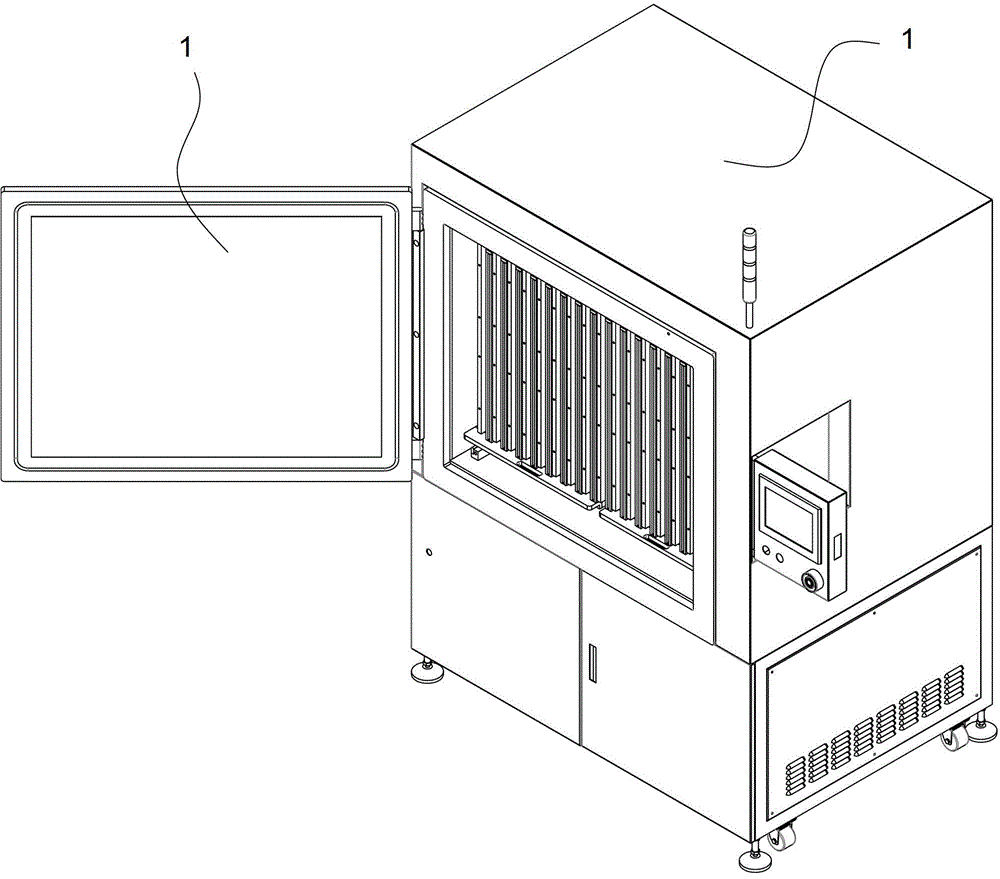
[0033] Such as Figure 1-2 As shown, a plasma processing system includes an outer frame 1, an electrode plate 2, a gas delivery pipeline 3, a vacuum system 6, and a material placement fixture 4; the electrode plate 2, the material placement fixture 4, and the gas delivery pipeline 3 are The provided air outlets are all located in the vacuum cavity 5 formed by the outer frame 1; Figure 4-5 As shown, the material placement fixture 4 is a frame structure, which is a product holder made of four solid metal materials, located between two corresponding electrode plates 2, and the gas delivery pipeline 3 is located between the material placement fixture 4 and Between the electrode plates 2, the air outlet is directly opposite to the frame 41 of the material placing fixture.

[0034] The vent hole is circular with a diameter of 1-2mm. The electrode area is 0.3-1.5 square meters, preferably 0.7 square mete...


PUM


Abstract

The invention discloses a plasma processing system with an airflow limiting mechanism, and belongs to the technical field of plasma processing. The plasma processing system comprises an outer frame, electrode plates, gas transmission pipelines, a vacuumizing system and material placement fixtures. The electrode plates, the material placement fixtures and vent holes in the gas transmission pipelines are positioned in a vacuum cavity body formed by the outer frame. Each material placement fixture has a frame-shaped structure, and is positioned between two opposite electrode plates. The gas transmission pipelines are positioned between the material placement fixtures and the electrode plates, and the vent holes of the gas transmission pipelines are opposite to frames of the material placement fixtures. The invention also discloses a plasma processing method. By the plasma processing system with the airflow limiting mechanism, a gas is uniformly distributed between the electrode plates, and is completely ionized to generate uniform a plasma gas, and a processed sample is subjected to plasma processing. The processed sample can be subjected to uniform plasma processing, so that the problem of non-uniformity of the plasma processing is solved, and plasma processing efficiency also can be improved.

Description

technical field [0001] The present invention relates to a plasma processing technology, in particular to a plasma processing system with a gas flow restriction mechanism capable of uniform gas distribution and a method thereof. Background technique [0002] At present, plasma treatment equipment is widely used in plasma cleaning, etching, plasma plating, plasma coating, plasma ashing and surface activation, modification and other occasions. Through its treatment, the wetting ability of the material can be improved, so that various materials can be coated, plated, etc., the adhesion and bonding force can be enhanced, and organic pollutants, oil or grease can be removed at the same time. [0003] However, in the existing plasma processing equipment, there is no gas flow restriction mechanism between all the electrodes, and the gas is not evenly distributed between every two electrodes. The gas can only be partially ionized between the two electrodes, and some The gas is sucke...

Claims


Application Information

Patent Timeline
Patent Type & Authority Patents(China)
IPC IPC(8): H01J37/32H05H1/24
Inventor 丁雪苗
Owner BOFFOTTO ELECTRONICS TECH
Why Eureka
Try Eureka