
Vertical orientation liquid crystal display

A liquid crystal display, vertical orientation technology, applied in the direction of instruments, nonlinear optics, optics, etc., can solve the problems of poor display performance, poor light transmission performance of liquid crystal display, poor display effect, etc., to achieve improved light transmission performance, transmittance Improve, enhance the effect of contrast

Active Publication Date: 2013-01-16
TRULY SEMICON
View PDF5 Cites 0 Cited by
  • Summary
  • Abstract
  • Description
  • Claims
  • Application Information

AI Technical Summary

Problems solved by technology

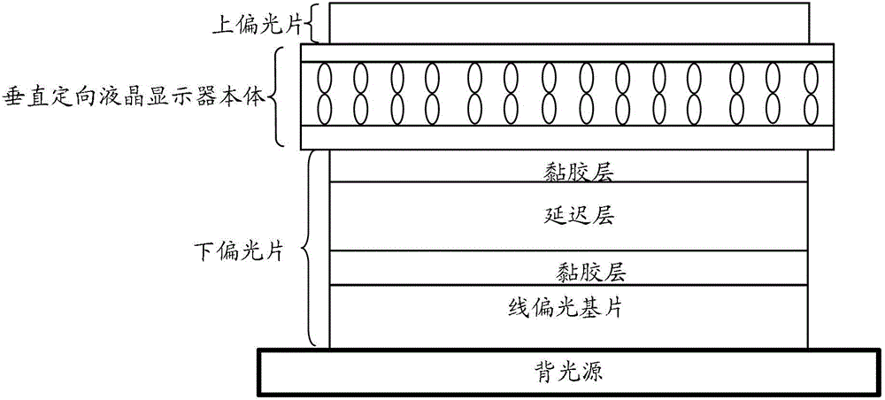
The inventors of the present invention found in the process of realizing the present invention that linear polarizers are respectively attached to the outer surfaces of the upper and lower transparent substrates in the prior art, and determined by the characteristics of the linear polarizers themselves, this liquid crystal The light transmission performance of the display is poor, and the display effect is poor, and this liquid crystal display with poor display effect is applied to the vehicle-mounted display device, and the vehicle-mounted display device itself often bumps and sways with the car, and its display The performance will become worse. For this reason, developing a liquid crystal display with high display performance has become an urgent and hard-working development goal of various liquid crystal display device manufacturers.

Method used


Image

  • Vertical orientation liquid crystal display
  • Vertical orientation liquid crystal display
  • Vertical orientation liquid crystal display

Examples


Embodiment Construction

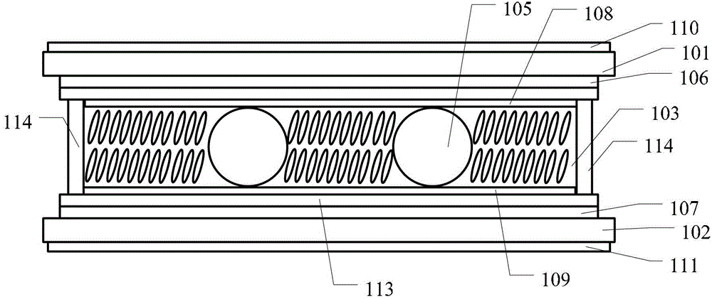
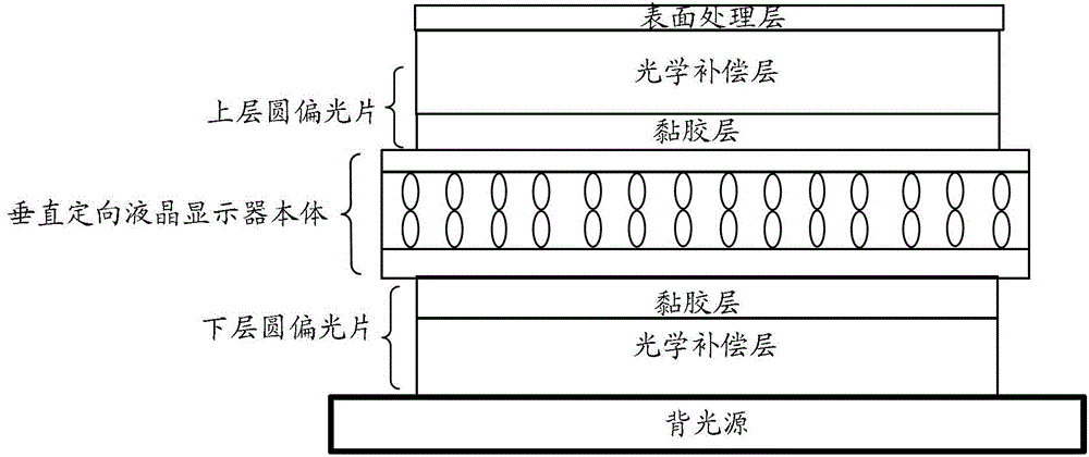
[0022] An embodiment of the present invention provides a vertically oriented liquid crystal display, which improves the light transmission performance of the product by matching a certain phase-compensated circular polarizer.

[0023] In order to make the purpose, features and advantages of the present invention more obvious and understandable, the technical solutions in the embodiments of the present invention will be clearly and completely described below in conjunction with the accompanying drawings in the embodiments of the present invention. Obviously, the following The described embodiments are only some, not all, embodiments of the present invention. All other embodiments obtained by those skilled in the art based on the embodiments of the present invention belong to the protection scope of the present invention.

[0024] For a vertically oriented liquid crystal display provided by an embodiment of the present invention, please refer to figure 1 As shown, it may mainly...


PUM


Abstract

The embodiment of the invention discloses a vertical orientation liquid crystal display, wherein a vertical orientation type liquid crystal layer is injected between an upper layer glass substrate and a lower layer glass substrate; the interior of the vertical orientation type liquid crystal layer comprises liquid crystal with negative anisotropy and a dielectric constant and plastic balls used for supporting; an upper layer conductive electrode is arranged on the lower surface of the upper layer glass substrate, and a lower layer conductive electrode is arranged on the upper surface of the lower layer glass substrate; an upper orientation layer is arranged between the upper layer conductive electrode and the vertical orientation type liquid crystal layer, and a lower orientation layer is arranged between the lower layer conductive electrode and the vertical orientation type liquid crystal layer; an upper layer circular polaroid is arranged on the upper surface of the upper layer glass substrate, and a lower layer circular polaroid is arranged on the lower surface of the lower layer glass substrate; a phase compensation value Delta n*d of the upper layer circular polaroid and the lower layer circular polaroid ranges from 110 nm to160 nm; and a refractive index of the upper layer circular polaroid and the lower layer circular polaroid in Z direction ranges from 1.4 to 1.8.

Description

technical field [0001] The invention relates to the technical field of liquid crystal display, in particular to a vertical alignment liquid crystal display. Background technique [0002] With the rapid development of the global automobile industry and the continuous update and change of consumer concepts in the automobile market, as liquid crystal display products develop increasingly rapidly, people's requirements for the performance of displays used in vehicle display devices have greatly increased. [0003] In the prior art, the liquid crystal display usually used for vehicle-mounted display devices mainly includes the following structure: an upper transparent substrate and a lower glass substrate, a liquid crystal layer is poured between the upper and lower transparent substrates, and the outer layer of the upper and lower transparent substrates Wired polarizers are respectively attached on the surface. The inventors of the present invention found in the process of real...

Claims


Application Information

Patent Timeline
IPC IPC(8): G02F1/13363G02F1/1335G02F1/139
Inventor 李锋张文峰苏初榜谢雄才何基强李建华
Owner TRULY SEMICON
Learn More