Eureka AIR delivers breakthrough ideas for toughest innovation challenges, trusted by R&D personnel around the world.

Flat plate collector with heat pipes

A flat-plate collector and heat pipe technology, which is applied to solar collectors, solar collectors using working fluids, heating devices, etc., can solve the problems of easy freezing and cracking of collector pipes, easy falling off, and high price. , to avoid the problem of firmness and thermal resistance of laser welding or ultrasonic welding, improve heat transfer effect, and improve reliability

Inactive Publication Date: 2013-01-16
王超生 +1
View PDF7 Cites 4 Cited by
  • Summary
  • Abstract
  • Description
  • Claims
  • Application Information

AI Technical Summary

Problems solved by technology

Its disadvantages are: the upper collector runner, the lower collector runner and the middle collector branch pipe are filled with water, which is easy to freeze and crack the collector pipe in cold weather; water is prone to scale in the collector runner for a long time, which will affect the collector Heat exchange efficiency; the heat collecting plate and the heat collecting flow channel are welded, which is easy to fall off, and the thermal resistance is large; because the copper flow channel is used, the price is expensive

Method used


Image

  • Flat plate collector with heat pipes
  • Flat plate collector with heat pipes
  • Flat plate collector with heat pipes

Examples


no. 1 example

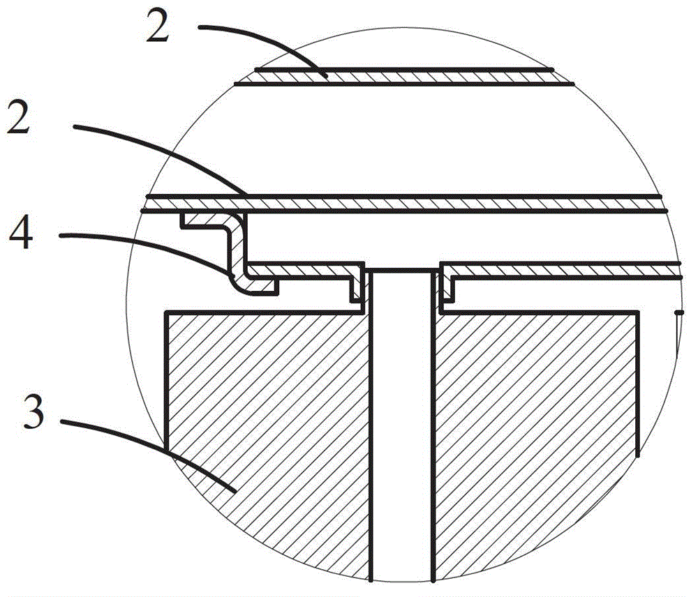
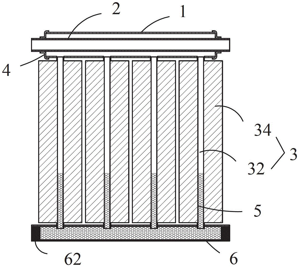
[0025] The heat pipe flat plate heat collector of the present invention includes an outer frame, high light-transmitting tempered glass is inlaid on the outer frame, and a heat-absorbing plate core is installed under the tempered glass, please refer to the same time figure 1 and figure 2 As shown, the heat absorbing plate core includes an upper communication header 1 , a heat exchange tube 2 and a heat collection tube 3 . The heat collecting tube 3 includes a heat collecting flow channel 32 and heat collecting fins 34 arranged on both sides of the heat collecting flow channel 32 .

[0026] The heat exchange tube 2 is arranged inside the upper communication header 1, and the tail end and the head end of the heat exchange tube 2 extend out of the upper communication header 1, and the two ends of the upper communication header 1 are sealed with the heat exchange tube 2, as In an optional solution, the upper communication header 1 and the heat exchange tube 2 are welded through ...

no. 2 example

[0030] see image 3 As shown, the difference between this embodiment and the above-mentioned first embodiment is that the heat pipe flat collector further includes a lower communication header 6 , and both ends of the lower communication header 6 are sealed with sealing plugs 62 .

[0031] In the above two embodiments, the heat collecting tube 3 is formed by one-time extrusion, that is, the heat collecting runner 32 and the heat collecting fins 34 are integrally formed. Compared with the use of copper, the production cost is reduced.

[0032] The heat collecting fins 34 of adjacent heat collecting tubes 3 can be separated by a small distance, such as figure 1 and image 3 As shown in , it is also possible to overlap each other, as in Figure 4 shown in .

[0033] And the structure of heat collecting tube 3 can have many kinds, as Figures 5 to 12 shown.

[0034] Figure 5 The heat collecting runner 32 of the shown heat collecting tube 3 is a cylindrical hollow structure...


PUM


Abstract

The invention discloses a flat plate collector with heat pipes. An absorber plate core of the flat plate collector comprises an upper communicated header, a heat exchange pipe and heat collecting pipes; each heat collecting pipe comprises a heat collecting runner and heat collecting fins arranged on the two sides of the heat collecting runner; the heat exchange pipe is arranged in the upper communicated header, and the tail end and the head end of the heat exchange pipe extend out of the upper communicated header; the two ends of the upper communicated header are sealed with the heat exchange pipes; the upper communicated header is arranged above the heat collecting runners and communicated with a plurality of heat collecting runners; the upper openings of the heat collecting runners are lower than the bottom of the upper communicated header, and the bottom ends of the heat collecting runners are sealed; the heat collecting runners are filled with heat pipe media; and the heat collecting runners and the heat collecting fins are of an integral structure. The flat plate collector has the advantages that as the heat collecting pieces are formed through one-time extrusion, the problems on firmness and heat resistance caused by laser welding or ultrasonic welding are avoided; the defects of frost cracking of a common heat collector in winter and scaling of a pipeline of a common flat plate collector are overcome; and a channel can be formed in each heat collecting runner, and thus the heat transfer effect of the flat plate collector can be improved effectively.

Description

technical field [0001] The invention relates to a solar heat collector, in particular to a flat plate heat collector. Background technique [0002] The flat-plate solar collectors commonly used in the market currently include copper runners and heat-absorbing plates with heat-absorbing coatings. The upper heat collector runner, the lower heat collector runner and the middle heat collector branch pipe form an "H" type copper runner, and the aluminum plate or copper plate with heat absorbing coating is welded on the heat collector branch pipe by ultrasonic or laser welding. Water is stored in the copper flow channel. When the sun shines on the plate with heat-absorbing coating to heat it, the plate then transmits heat to the heat collecting branch pipe to heat the water inside the branch pipe. Hot water will store heat in the water tank through circulation, forming a commonly used household solar water heater system. Its disadvantages are: the upper collector runner, the low...

Claims


Application Information

Patent Timeline
Patent Type & Authority Applications(China)
IPC IPC(8): F24J2/26F24J2/32F24J2/46F24S10/75F24S10/95
CPCY02E10/44F24J2/32F24J2/26F24S10/75F24S10/95
Inventor 王超生阮国成
Owner 王超生
Why Eureka
Eureka Blog
Learn More