
Gas cutting method, gas cutting device and cutting nozzle

A nozzle and gas cutting technology, applied in combustion methods, welding/cutting media/materials, lighting and heating equipment, etc., can solve the problems of reducing the ratio of mixed hydrocarbon gas or liquefied petroleum gas, low cutting performance, explosion, etc. Superior cutting performance, improved safety, easy to adjust results

Active Publication Date: 2017-06-30
NIPPON SANSO CORP
View PDF3 Cites 0 Cited by
  • Summary
  • Abstract
  • Description
  • Claims
  • Application Information

AI Technical Summary

Problems solved by technology

[0013] However, in the gas cutting methods described in Patent Document 1 and Patent Document 2, it was confirmed that the higher the concentration of hydrocarbon gas mixed in hydrogen, the lower the cutting performance such as cutting speed. In order to fully exert the cutting performance of hydrogen gas, it is necessary to reduce the mixing The ratio of hydrocarbon gas or LPG
[0014] On the other hand, when 100% hydrogen is used as the fuel gas without mixing hydrocarbon gas or liquefied petroleum gas, there is a problem that the preheating flame cannot be adjusted because the white center at the tip of the nozzle cannot be seen.
[0015] In addition, using a mixed gas of oxygen and hydrogen, which is an explosive gas, has the entire supply path of the hydrogen and oxygen gas when the pressure of the hydrocarbon gas drops or a mixing failure occurs due to equipment (for example, Figure 9 The whole of the supply route L101 shown) has the problem of explosion hazard

Method used


Image

  • Gas cutting method, gas cutting device and cutting nozzle
  • Gas cutting method, gas cutting device and cutting nozzle
  • Gas cutting method, gas cutting device and cutting nozzle

Examples


Embodiment Construction

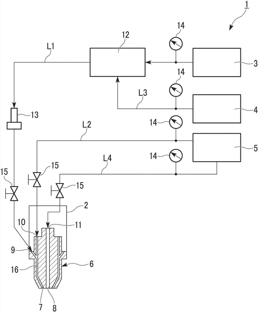
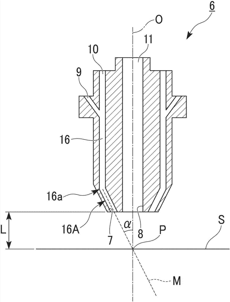
[0081] Hereinafter, a gas cutting method to which one embodiment of the present invention is applied will be described together with a gas cutting device and a cutting nozzle used therefor, using the drawings. In addition, in the drawings used in the following description, in order to make the characteristics easier to understand, the characteristic parts may be enlarged and shown for convenience, and the dimensional ratio of each component is not limited to be the same as the actual one.

[0082] figure 1 It is a system diagram which shows the gas cutting apparatus used for the gas cutting method which concerns on one Embodiment of this invention. Such as figure 1 As shown, the gas cutting device 1 of the present embodiment has: a cutting torch 2 with a cutting nozzle 6, the cutting nozzle 6 is provided with a preheating hole 7 and a cutting oxygen hole 8; a hydrogen supply source 3 for supplying hydrogen; Hydrocarbon gas supply source 4; oxygen supply source 5 for supply...


PUM


Abstract

The invention provides a gas cutting method, a gas cutting device and a cutting nozzle. The gas cutting method is characterized in that hydrogen is mixed with hydrocarbon gas to obtain fuel gas, and the fuel gas and preheating oxygen are injected from the front end of the cutting nozzle. mixing and igniting the formed preheating flame to heat the workpiece, spraying cutting oxygen to the heated workpiece to cut the workpiece, and the content of hydrocarbon gas in the fuel gas is more than 0% by volume and not more than 4% by volume .

Description

technical field [0001] The invention relates to the improvement of a gas cutting method, a gas cutting device and a cutting nozzle. [0002] this application claims priority based on Japanese Patent Application No. 2010-097258 for which it applied to Japan on April 20, 2010, and uses the content here. Background technique [0003] When cutting workpieces such as steel plates, the cutting start point of the workpiece is heated to a temperature capable of oxidation reaction with a preheating flame, and high-purity oxygen is injected to the heated part to burn and melt the heated part, thereby cutting the workpiece. Gas cutting method being widely used. [0004] In order to form a preheating flame in this gas cutting method, hydrocarbon gases (LPG, LNG, city gas, acetylene, propane, methane, ethylene, propylene, butane, etc., or their mixed gases) are usually used in the preheating hole as Fuel gas and preheated oxygen for efficient combustion of the fuel gas. [0005] In re...

Claims


Application Information

Patent Timeline
Patent Type & Authority Patents(China)
IPC IPC(8): B23K7/10
CPCB23K7/00B23K35/228B23K35/38F23D14/22F23D14/32F23D14/42F23K2900/05004F23D14/54
Inventor 佐藤丰幸山本康之加藤隆长堀正幸上木原洋丘武田隆志
Owner NIPPON SANSO CORP
Learn More