Exhaust gas catalytic purging unit using selective reduction catalyst, exhaust gas purging method, and diesel automobile equipped with exhaust gas catalytic purging unit

A catalyst device, exhaust gas purification technology, applied in catalyst activation/preparation, catalyst regeneration/reactivation, exhaust device, etc., can solve problems such as engine output power reduction and filter clogging

Inactive Publication Date: 2013-01-09
N E CHEMCAT
View PDF16 Cites 11 Cited by
  • Summary
  • Abstract
  • Description
  • Claims
  • Application Information

AI Technical Summary

Problems solved by technology

The filtered particulate components are accumulated in the filter, but if the particulate components continue to accumulate in the filter, the filter will be clogged and the output power of the engine will be reduced.

Method used


Image

  • Exhaust gas catalytic purging unit using selective reduction catalyst, exhaust gas purging method, and diesel automobile equipped with exhaust gas catalytic purging unit
  • Exhaust gas catalytic purging unit using selective reduction catalyst, exhaust gas purging method, and diesel automobile equipped with exhaust gas catalytic purging unit
  • Exhaust gas catalytic purging unit using selective reduction catalyst, exhaust gas purging method, and diesel automobile equipped with exhaust gas catalytic purging unit

Examples


Embodiment 1-6

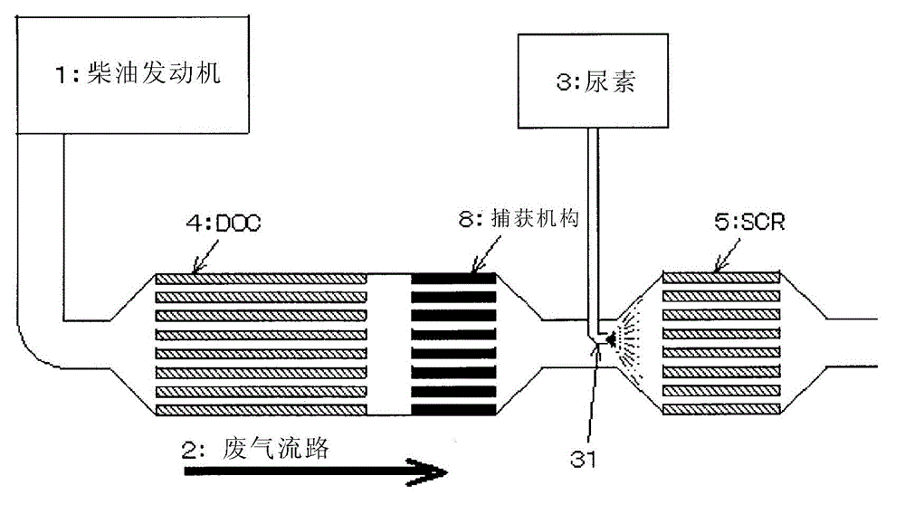
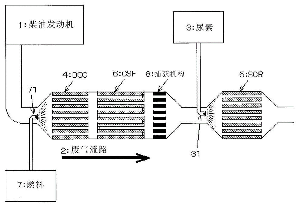
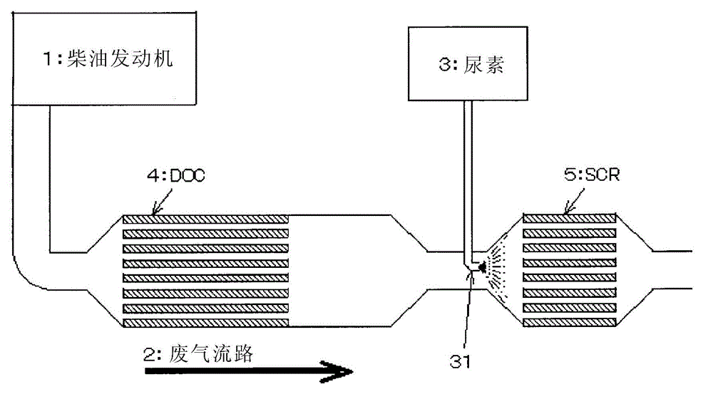
[0209] The above-mentioned oxidation catalyst 1, oxidation catalyst 2, oxidation catalyst 3, trapping mechanism 1, trapping mechanism 2, and SCR1 were arranged in an exhaust pipe (diameter 24 mm, length 700 mm) as shown in Table 2, and the exhaust gas catalyst of the present invention was obtained. device. Using this apparatus, aging was performed by circulating heated air at 900° C. for 20 hours at a flow rate of 10 [L / min]. In addition, the distance between the oxidation catalyst and the capture mechanism was 15 mm and the distance between the capture mechanism and the SCR 1 was 200 mm when aging was performed according to the examples. In addition, when using two oxidation catalysts, the distance between oxidation catalysts was 15 mm. In addition, in the burn-in test for the comparative example in which the trapping mechanism was not arranged, only the trapping mechanism was not disposed, and the arrangement was the same as the evaluation in the examples.

[0210] Table 2...

Embodiment 7

[0227] The above-mentioned oxidation catalyst 3 and capture mechanism 2 are arranged like "oxidation catalyst 3 + capture mechanism 2", aged under the aforementioned aging conditions, and the amount of precious metal adsorbed on the capture mechanism 2 is determined by ICP-AES (Inductively Coupled Plasuma-Atomic Emission Spectrometry, inductively coupled plasma-atomic emission spectrometry).

[0228] In addition, except that the capture mechanism 2 was not used, the same operation was carried out as in Examples 5 and 6, and oxidation catalysts 1 and 2 and SCR 1 were arranged in the exhaust pipe as shown in Table 2 to obtain an exhaust gas catalyst device for comparison. . Using this device, aging was similarly performed.

[0229] As a result, it was found that the amount of the Pt component in terms of metal was 15 ppm, and the amount of the Pd component in terms of metal was less than 1 ppm.

[0230] From this, it can be seen that the volatilization amount of the Pt compone...


PUM

PropertyMeasurementUnit
melting pointaaaaaaaaaa
thicknessaaaaaaaaaa

Abstract

Provided are: an exhaust gas catalytic purging unit capable of long-term efficient purging of microparticle components such as hydrocarbons, carbon monoxide, nitrogen oxides and soot contained in exhaust gas from a lean-burn engine; a method for purging exhaust gas using such an exhaust gas catalytic purging unit; and a diesel automobile equipped with this exhaust gas catalytic purging unit. An exhaust gas catalytic purging unit is provided in which an oxidation catalyst (DOC) comprising noble metal components for oxidation of nitrogen oxides (NOx) contained in exhaust gas emitted from a diesel engine, a reducing agent spray means for feeding a reducing agent selected from a urea component or an ammonia component, and a selective reduction catalyst (SCR) for reduction by bringing nitrogen oxides (NOx) into contact with the reducing agent are disposed in this order from the upstream side of an exhaust gas stream, wherein the selective reduction catalyst (SCR) is zeolite or crystalline metal aluminophosphate that does not contain a noble metal component, and a trap means for collecting the noble metal component evaporated from the oxidation catalyst (DOC) is disposed between the oxidation catalyst (DOC) and the selective reduction catalyst (SCR).

Description

technical field [0001] The present invention relates to an exhaust gas purifying catalyst device using a selective reduction catalyst, an exhaust gas purifying method, and a diesel vehicle equipped with an exhaust gas purifying catalyst device, and more particularly relates to a method capable of efficiently purifying hydrocarbons, An exhaust gas purifying catalyst device for purifying particulate components such as carbon monoxide, nitrogen oxides, and coal, an exhaust gas purifying method using such an exhaust gas purifying catalyst device, and a diesel automobile equipped with the exhaust gas purifying catalyst device. Background technique [0002] Exhaust gas discharged from boilers, gas turbines, or lean burners such as lean-burn gasoline engines and diesel engines contains various harmful substances derived from fuel and combustion air. Such harmful substances include hydrocarbons (HC), soluble organic fraction (Soluble Organic Fraction: also called SOF), coal (Soot), ...

Claims


Application Information

Patent Timeline
Patent Type & Authority Applications(China)
IPC IPC(8): B01D53/94B01D53/96B01J23/96B01J38/00F01N3/02F01N3/08F01N3/24F01N3/28
CPCB01D2255/2092B01J37/0215F01N13/02F01N2013/026B01D53/9418B01D2258/012B01J35/04B01D53/9477F01N3/035B01D2255/1023B01J35/1019F01N3/2066F01N2610/02B01J21/04B01J29/7615B01D2255/1021F01N3/0253B01D2255/502F01N3/106B01J37/0036B01D2251/2067B01D2251/208B01D2255/30Y02T10/24B01J37/038B01D2255/20738F01N2370/04B01J23/44B01J23/42B01J35/0006B01J37/0246B01J37/04F01N13/009F01N13/0097Y02T10/12Y02A50/20
Inventor 伴野靖幸永田诚
Owner N E CHEMCAT
Why Eureka
Try Eureka