
Pole plate assembling device of automatic piece coating machine

A technology of automatic wrapping machine and assembly device, which is applied in the field of wrapping machines, and can solve problems such as poor wrapping quality, health impact of operators, and low efficiency

Inactive Publication Date: 2013-01-09
浙江长兴奥利尔科技股份有限公司
View PDF4 Cites 3 Cited by
  • Summary
  • Abstract
  • Description
  • Claims
  • Application Information

AI Technical Summary

Problems solved by technology

[0002] There is a "wrapping" process in the current battery production process, which is to assemble the positive electrode sheet, negative electrode sheet, and separator paper into an electrode group. The separator paper is sandwiched between the positive electrode sheet and the negative electrode sheet. The traditional "wrapping sheet" "The process is mostly manual operation. The operator first takes a piece of negative electrode, sandwiches the positive electrode with the cut separator paper and stacks it on the negative electrode to ensure that there is separator paper between each group of positive and negative electrodes. , cycle the above operations to complete the whole package and assembly, not only the efficiency is low, but also the quality of the package is not high, and the lead dust falling on the pole piece will also affect the health of the operators
The existing disclosed automatic wrapping machine adopts an automated processing method, which can complete the wrapping of the positive plate (negative plate) in sequence, and the stacked assembly of the wrapping plate and the negative plate. When assembling, place the Assembling the box, the electrode group sent from the discharge end falls into the assembly box according to gravity and is automatically stacked into a pole group. Since the assembly box can only carry a rated number of plates at a time, if the number of plates in the pole group increases, only It can be replaced with a longer assembly box, which is inconvenient to operate

Method used


Image

  • Pole plate assembling device of automatic piece coating machine

Examples


Embodiment Construction

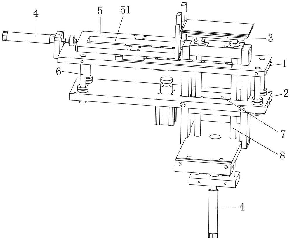
[0012] The invention provides a pole plate assembly device of an automatic wrapping machine. The pole plate assembly device is installed at the discharge port of the wrapping machine. The pole plate assembly device includes a support bracket, a support cylinder and a support plate. The support The cylinder drives the supporting plate up and down through the transmission column, and the supporting plate corresponds to the discharge port of the wrapping machine. The supporting plate is set under the outlet of the wrapping machine. When the plate group falls from the outlet of the wrapping machine, the supporting plate supports the plate group, and the supporting cylinder drives the supporting plate down by one level through the transmission column. The height of the plate group allows space for one plate group to hold the next plate group, and the height of the support plate can be adjusted by the support cylinder to meet the number of plates in the pole group. .

[0013] The t...


PUM


Abstract

The invention discloses a pole plate assembling device of an automatic piece coating machine. The pole plate assembling device is arranged at a discharge port of the piece coating machine and comprises a retainer bracket, a retainer cylinder and a retainer plate, wherein the retainer cylinder drives the retainer plate to lift and descend through a transmission column; and the retainer plate is opposite to the discharge port of the piece coating machine. When a pole plate group falls down from the discharge port of the piece coating machine, the retainer plate supports the pole plate group, the retainer cylinder drives the retainer plate to descend by the height of one pole plate group through the transmission column, the space of one pole plate group is made to support the subsequent pole plate group, the descending height or lifting height of the retainer plate can be regulated by the retainer cylinder, and requirements on the quantity of pole plates in a pole group are met.

Description

technical field [0001] The invention relates to a wrapping machine, in particular to a pole plate assembly device of an automatic wrapping machine. Background technique [0002] There is a "wrapping" process in the current battery production process, which is to assemble the positive electrode sheet, negative electrode sheet, and separator paper into an electrode group. The separator paper is sandwiched between the positive electrode sheet and the negative electrode sheet. The traditional "wrapping sheet" "The process is mostly manual operation. The operator first takes a piece of negative electrode, sandwiches the positive electrode with the cut separator paper and stacks it on the negative electrode to ensure that there is separator paper between each group of positive and negative electrodes. , cycle above-mentioned operation, finish whole wrapping and assembly, not only efficiency is low, and wrapping quality is not high, and the lead dust that falls on pole piece also c...

Claims


Application Information

Patent Timeline
IPC IPC(8): H01M10/14
CPCY02E60/126Y02E60/10Y02P70/50
Inventor 薛禹沈志国
Owner 浙江长兴奥利尔科技股份有限公司
Learn More