Infrared optical window and manufacturing method thereof

An infrared optical window, photoresist layer technology, applied in optics, optical components, instruments, etc., can solve the problems of changing the refractive index of the anti-reflection layer, surface unevenness, easy to sink, etc., and achieves insensitivity to changes in the working environment. The method is simple and the effect of increasing the service life

Inactive Publication Date: 2015-05-06
UNIV OF ELECTRONICS SCI & TECH OF CHINA
View PDF9 Cites 0 Cited by
  • Summary
  • Abstract
  • Description
  • Claims
  • Application Information

AI Technical Summary

Problems solved by technology

[0003] However, although the windows with sub-wavelength structure have high infrared transmittance, the following problems will occur in the actual use process: First, the dust particles in the use environment are easy to be trapped in the structure, making the refractive index of the anti-reflection layer Changes occur, the window is polluted, and the infrared window cannot be cleaned by ordinary wiping methods, thereby affecting the infrared transmittance of the window
Second, the size of the sub-wavelength structure of the infrared window is too small, and the surface structure of the window is easily damaged in the event of an accidental bump. Physical damage will also change the refractive index of the anti-reflection layer, affecting the service life of the window and even causing the window to fail.
However, due to the small uneven structure on the surface of the subwavelength structure, the surface after vapor deposition will also be uneven, which will not protect the subwavelength structure of the infrared window, so this method cannot be used to make a protective layer of the subwavelength structure.
In the prior art, there is no relevant research report on how to protect the sub-wavelength anti-reflection structure of the infrared window

Method used


Image

  • Infrared optical window and manufacturing method thereof
  • Infrared optical window and manufacturing method thereof
  • Infrared optical window and manufacturing method thereof

Examples


Embodiment Construction

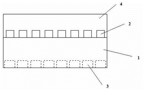
[0021] Such as figure 1 As shown, in the embodiment of the present invention, a method for manufacturing an infrared optical window includes step 10 , step 12 , step 14 and step 16 .

[0022] Step 10: providing an infrared optical window substrate.

[0023] In an embodiment of the present invention, firstly, a substrate for manufacturing an infrared optical window, that is, an infrared optical window substrate is provided. In the embodiment of the present invention, the substrate can be made of any material suitable for manufacturing infrared optical windows, such as silicon, germanium, sapphire, ZnS (zinc sulfide), ZnSe (selenium sulfide), Chalcogenide Glasses (black diamond) etc.

[0024] Step 12: forming a first anti-reflection structure on the incident surface.

[0025] In use, the infrared optical window is incident on one side and exits on the other side, so it has an incident surface and an exit surface. Correspondingly, since the infrared optical window is made bas...


PUM

PropertyMeasurementUnit
thicknessaaaaaaaaaa
thicknessaaaaaaaaaa

Abstract

The embodiment of the invention discloses an infrared optical window and a manufacturing method of the infrared optical window. The manufacturing method comprises the following steps: providing an infrared optical window substrate; forming a first anti-reflection structure on an incident plane; forming a second anti-reflection structure on an emergence plane; and forming a thin polymer film protective layer on the incident plane on which the first anti-reflection structure is formed. According to the embodiment of the invention, the thin film protective layer formed by a polymer material with high infrared transmittance is formed on the anti-reflection structure on the incident plane. The thin film protective layer has the advantages of no water and moisture absorption and stable mechanical properties, and is not sensitive to changed working environments and small in internal stress, average infrared transmittance at 8-12 mum wave bands achieves above 85%, refractive index is moderate, preparation method is simple, and cost is low. The structure is utilized to prevent the anti-reflection structures from environmental pollutions and physical damages, effectively improves the reliability of a window, and prolongs the service life of the window.

Description

technical field [0001] The invention relates to the field of infrared optical devices, in particular to an infrared optical window and a manufacturing method thereof. Background technique [0002] Since traditional infrared optical window materials have a large reflection coefficient, surface anti-reflection treatment is required when used as an infrared optical window. The usual anti-reflection treatment method is to make a sub-wavelength anti-reflection structure on the surface of the infrared optical window. Theoretically, the infrared window with sub-wavelength anti-reflection structure can achieve a maximum infrared transmittance of 99.5% in the 8-12um band, and an average transmittance of more than 95%. [0003] However, although the windows with sub-wavelength structure have high infrared transmittance, the following problems will occur in the actual use process: First, the dust particles in the use environment are easy to be trapped in the structure, making the refr...

Claims


Application Information

Patent Timeline
Patent Type & Authority Patents(China)
IPC IPC(8): G02B1/11G02B1/14
Inventor 何少伟陈鹏杰王明星胡庆徐向东李伟
Owner UNIV OF ELECTRONICS SCI & TECH OF CHINA
Why Eureka
Try Eureka