
Assembly type biomass briquette fuel steam boiler

A molding fuel and steam boiler technology, which is applied to water tube steam boilers, steam boilers, boiler water pipes, etc., can solve the problems of difficult installation of partition wall bricks, heavy structures, complex structures, etc., to facilitate ignition and combustion, and increase air flow Disturbance, effect of improving uniformity

Inactive Publication Date: 2012-12-26
广州贝龙环保热力设备股份有限公司
View PDF12 Cites 0 Cited by
  • Summary
  • Abstract
  • Description
  • Claims
  • Application Information

AI Technical Summary

Problems solved by technology

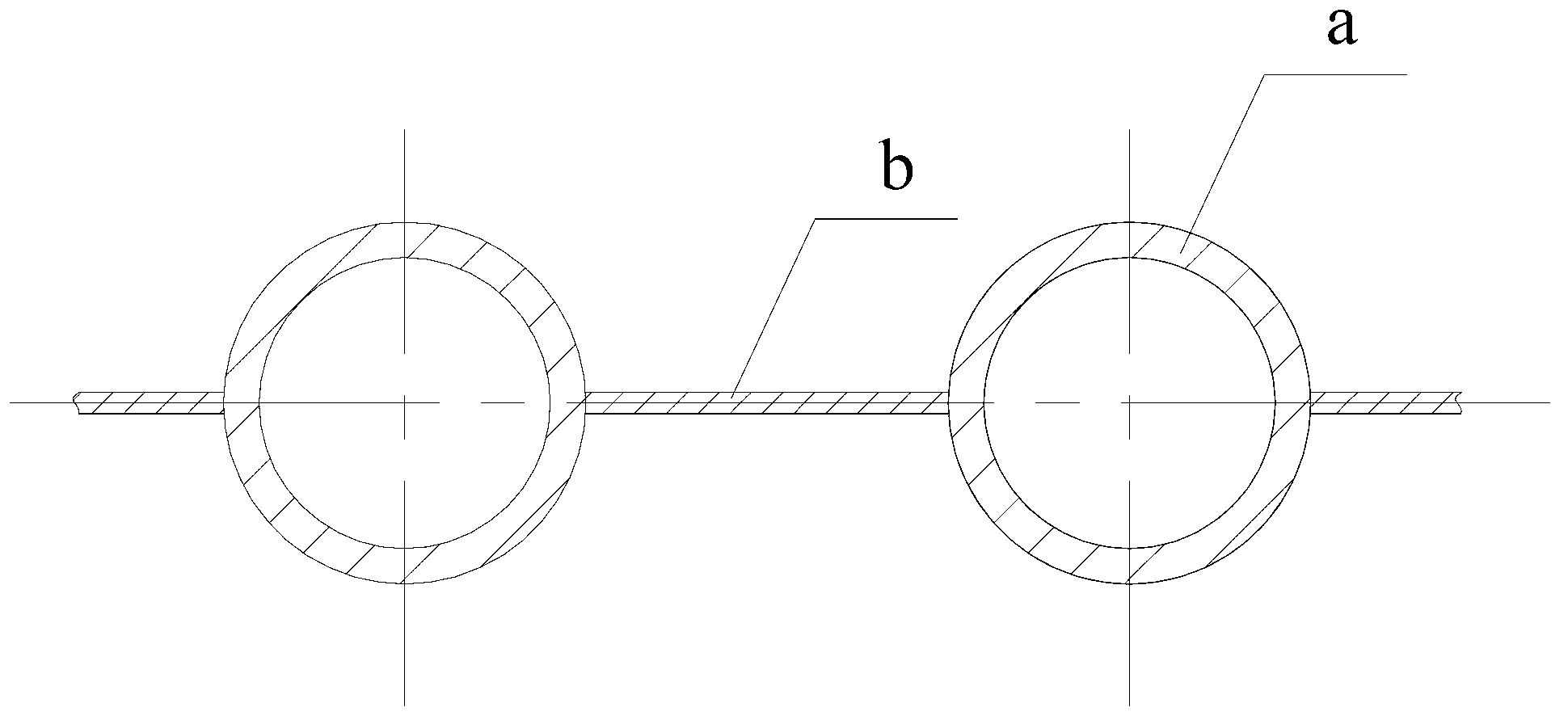
Membrane wall type convection tube bundles are suitable for processing with membrane wall special welding machines, and the structure is also a bit bulky. At the same time, due to the objective influence of processing errors, the nozzle spacing of membrane wall type convection tube bundles will be different from the openings of the upper and lower drums. There is an error in the spacing, and it needs to be corrected during on-site installation, which brings certain difficulties to the installation; and it is a whole piece after installation. When one of the pipes a is damaged in the future, the flat steel b connected to the damaged pipe a should be removed. It can only be removed by cutting it off. After replacing the new pipe a, it is necessary to weld the new pipe a to the flat steel b. It is very difficult to operate in a small space in the boiler, and it will also bring difficulties to future maintenance.
[0006] The partition wall made of refractory bricks needs to be specially customized partition wall bricks, and the structure will be more complicated, and the partition wall bricks will be added, and the weight will increase a lot; It is also quite difficult to install the partition wall tiles in the convection tube bundle, especially when it is installed in the middle of the furnace

Method used


Image

  • Assembly type biomass briquette fuel steam boiler
  • Assembly type biomass briquette fuel steam boiler
  • Assembly type biomass briquette fuel steam boiler

Examples


Embodiment Construction

[0027] Embodiments of the present invention will now be described with reference to the drawings, in which like reference numerals represent like elements.

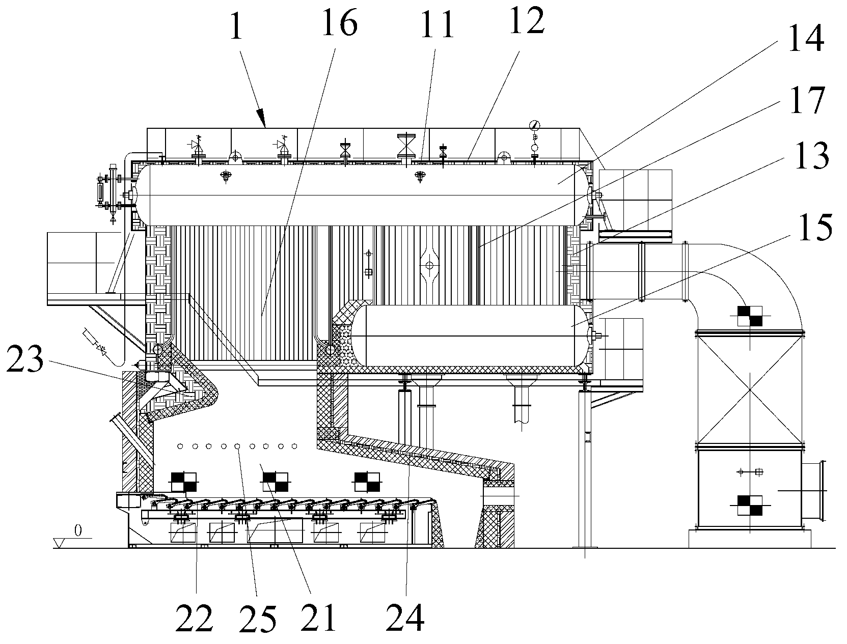
[0028] Please refer to Figure 2-4 , the assembled biomass briquette fuel steam boiler includes a boiler body 1 and a combustion device 2 located below the boiler body 1 .

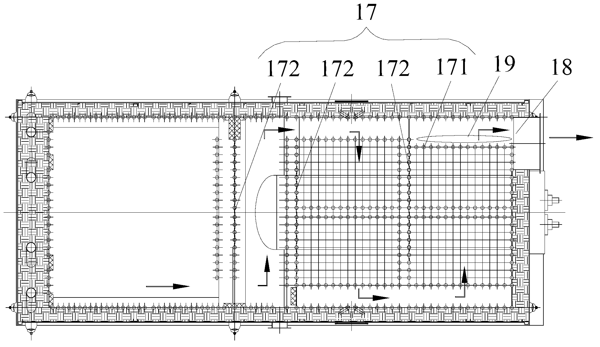
[0029] The boiler body 1 includes a bracket 11 , a shell 12 , a furnace wall 13 , an upper drum 14 , a lower drum 15 , a membrane wall 16 and a convection tube bundle 17 . The convection tube bundle 17 is located inside the membrane wall 16, the membrane wall 16 is located between the upper and lower drums 14, 15, and the furnace wall 13 is wrapped around the membrane wall 16 and the membrane wall 16. The upper and lower drums 14 and 15 are outside, the shell 12 is wrapped on the outside of the furnace wall 13 , and the bracket 11 is arranged inside the shell 12 . The bracket 11, the casing 12, the furnace wall 13, the upper drum 14, the lower drum ...


PUM


Abstract

The invention discloses an assembly type biomass briquette fuel steam boiler which comprises a boiler body and a combustion device located below the boil body. The combustion device is provided with a hearth, the boiler body comprises a support, a casing, a boiler wall, an upper boiler barrel, a lower boiler barrel, a film type wall and a convection tube bundle. The convection tube bundle is located on the inner side of the film type wall located between the upper boiler barrel and the lower boiler barrel, the boiler wall is wrapped on the outer sides of the film type wall, the upper boiler barrel and the lower boiler, the casing is wrapped on the outer side of the boiler wall, the support is arranged in the casing, the support, the casing, the boiler wall, the upper boiler barrel, the lower boiler barrel, the film type wall and the convection tube bundle are combined into a whole, and the height of the hearth is 4-5m. The assembly type biomass briquette fuel steam boiler can ensure sufficient combustion, prevents black smoke, and is light in weight and convenient to install and maintain.

Description

technical field [0001] The invention relates to an industrial steam boiler, in particular to an assembled biomass molding fuel steam boiler. Background technique [0002] Biomass fuel comes from a wide range of sources, and has the characteristics of low ash content and less pollution emissions after combustion, but has defects such as low calorific value and high water content, which make stable combustion difficult. Biomass fuels are dried, processed and formed into granules or blocks, and the flaws will disappear completely. This kind of biomass fuels has a wide range of sources and is a renewable energy source. It can achieve "zero emissions" during the combustion process. No pollutant emission, and the cost is lower than that of electricity, fuel oil and gas as fuel. It is a new type of fuel vigorously advocated and promoted by the country. [0003] Due to the characteristics of high volatile content of biomass briquette fuel and long flame during combustion, the tradi...

Claims


Application Information

Patent Timeline
Patent Type & Authority Applications(China)
IPC IPC(8): F22B21/04F22B31/00F22B37/10
Inventor 梁福任芦茂国陈润泉
Owner 广州贝龙环保热力设备股份有限公司
Learn More