
Automatic coupling device from optical fiber laser device to single mode optical fiber

A fiber laser and single-mode fiber technology, applied in the coupling direction of optical waveguide, etc., can solve the problems that the high coupling efficiency of the coupling element cannot be adjusted, the coupling efficiency cannot be further improved, and it is easily affected by the external environment, etc., to achieve precise automatic adjustment function , precise laser mode adjustment, and reliable operation

Inactive Publication Date: 2014-11-12
TAIYUAN UNIV OF TECH
View PDF6 Cites 0 Cited by
  • Summary
  • Abstract
  • Description
  • Claims
  • Application Information

AI Technical Summary

Problems solved by technology

However, the core diameter of the single-mode optical fiber is small, about 8-10m, and there is only one transmission mode, and the mechanical device used in the above-mentioned prior art is difficult to realize the movement with an accuracy of up to the order of microns, resulting in that the coupling efficiency cannot be further improved , the adjustment process is complex and has high requirements for the user, and the coupling element cannot be adjusted in real time according to changes in external conditions to maintain high coupling efficiency and is easily affected by the external environment

Method used


Image

  • Automatic coupling device from optical fiber laser device to single mode optical fiber

Examples


Embodiment approach 1

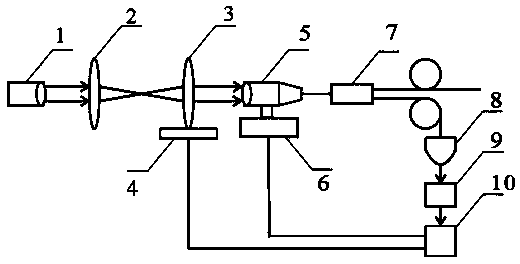
[0024] The mode conversion optical part is to convert the laser mode to meet the optical fiber transmission mode, and the automatic adjustment part is to control the mode conversion optical device with an accuracy up to micron and can have the function of automatic real-time adjustment to make the mode conversion optical system work at the best state to form an automatic coupling device in which the laser mode satisfies the optical fiber transmission mode to the greatest extent. The specific composition of this device is as follows:

[0025] The automatic coupling device of the present invention is composed of a first optical fiber collimator 1, a first convex lens 2, a second convex lens 3, a one-dimensional piezoelectric ceramic 4, a second optical fiber collimator 5, a two-dimensional piezoelectric ceramic 6, a single-mode A fiber coupler 7, a photodetector 8, a controller 9 and a driver 10 form a closed-loop control system, the input end of the fiber collimator 1 is connec...


PUM

PropertyMeasurementUnit
transmittivityaaaaaaaaaa

Abstract

The invention discloses an automatic coupling device from an optical fiber laser device to a single mode optical fiber. An input end of a first optical fiber collimator is connected with an output end of the optical fiber laser device; a collimating laser beam is output to a telescope system composed of a first convex lens and a second convex lens fixed to a one-dimensional piezoelectric ceramic translation table, and the collimating laser beam is coupled to the single mode optical fiber through a second optical fiber collimator arranged on a two-dimensional piezoelectric ceramic translation table; the collimating laser beam is divided into two paths through a single mode optical fiber coupler, wherein one path is converted into an electric signal through a photoelectric detector, the electric signal enters into a controller, the controller sends a control signal according to a value of the photoelectric signal to control a driver to drive a one-dimensional piezoelectric ceramic and a two-dimensional piezoelectric ceramic so as to form a closed-loop control system, and the other path is output for use. The automatic coupling device has the advantages of high structural coupling efficiency, self-adaptive temperature, external-environment-change such as vibration and the like resistance, reliable running, low fault rate and the like. The automatic coupling device is widely applied to the fields of precise light spectrum, quantum optics and others using the optical fiber laser device.

Description

technical field [0001] The present invention relates to a coupling device from a fiber laser to a single-mode fiber, further comprising a fiber collimator to roughly adjust the laser mode output by the fiber laser, a telescope system to fine-tune the laser mode, and a piezoelectric ceramic The resulting micro-displacement makes the coupling lens and coupling spot move within the micron level, so that the laser mode can meet the transmission mode of the single-mode fiber to the greatest extent, so as to realize the coupling of the fiber laser to the single-mode fiber, and use real-time feedback to adjust the coupling efficiency. The automatic coupling system is widely used in fields such as spectroscopy, quantum optics, and optical communication that use fiber lasers. Background technique [0002] Fiber lasers have the advantages of stable performance, high output power, good spectral characteristics, and portability, and are currently one of the most promising lasers. With ...

Claims


Application Information

Patent Timeline
Patent Type & Authority Patents(China)
IPC IPC(8): G02B6/42
Inventor 李国辉陈钰水崔艳霞
Owner TAIYUAN UNIV OF TECH
Learn More