
Full-digital proportion integration differentiation (PID) controlled light-emitting diode (LED) light source driver

A technology of LED light source and LED drive, applied in the direction of light source, electric light source, lighting device, etc., can solve the problems of complex manufacturing process, inconvenient control and quantitative management of analog circuit, large size of driving circuit, etc., to ensure service life and reliability. , Easy to control and quantitative management, stable effect of drive control

Inactive Publication Date: 2012-12-12
JIANGMEN LIANCHUANG DEV
View PDF6 Cites 6 Cited by
  • Summary
  • Abstract
  • Description
  • Claims
  • Application Information

AI Technical Summary

Problems solved by technology

First of all, the control method of the traditional LED light source driving scheme is simple, and the LED working characteristics require a stable working current. However, due to the unstable mains voltage, the life and reliability of the LED light source driver are greatly reduced, and the output current often varies with the supply voltage. The change will produce large fluctuations, which will cause flickering when the LED is working, which indirectly affects the service life of the LED light source; secondly, some high-power LEDs require high-quality, dedicated circuit drivers. These analog integrated circuits are not only complicated in manufacturing process, but also The production cost is high, and the drive circuit is large in size, which is not conducive to mass production; finally, the analog circuit is not convenient for control and quantitative management, and it is difficult to meet the needs of diversified applications in today's market

Method used

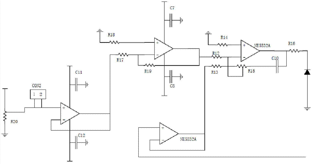
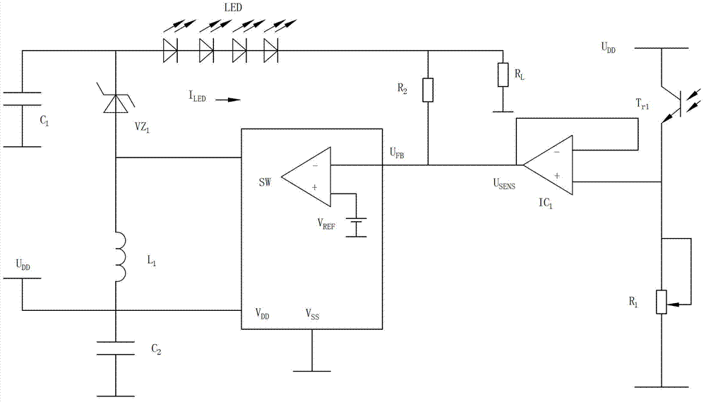

Image

  • Full-digital proportion integration differentiation (PID) controlled light-emitting diode (LED) light source driver
  • Full-digital proportion integration differentiation (PID) controlled light-emitting diode (LED) light source driver
  • Full-digital proportion integration differentiation (PID) controlled light-emitting diode (LED) light source driver

Examples


Embodiment Construction

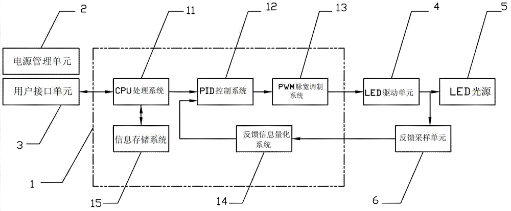
[0019] refer to figure 1 , an all-digital PID control LED light source driver of the present invention includes a user interface unit 3, a control processing unit 1, an LED drive unit 4, an LED light source 5 and a power management unit 2, wherein the core part of the control processing unit 1 includes an integrated single-chip microcomputer The CPU processing system 11, the PID control system 12, the PWM pulse width modulation system 13, the feedback information quantization system 14 and the information storage system 15 in it.

[0020] In the present invention, the control processing unit 1 performs information processing and control by means of a single-chip microcomputer, and writes a software PID controller through a software program, thereby realizing full-digital PID control. The PID control system 12 calculates the duty ratio data of the current modulation according to the given control amount and feedback amount, and transmits it to the PWM pulse width modulation sys...


PUM


Abstract

The invention discloses a full-digital proportion integration differentiation (PID) controlled light-emitting diode (LED) light source driver, comprising a control processing unit, a user interface unit, an LED driving unit, an LED light source and a power supply management unit, wherein the control processing unit comprises a central processing unit (CPU) processing system, a PID control system, a pulse-width modulation (PWM) system and a feedback information quantification system which are integrated in a single chip microcomputer; and an output end of the LED driving unit is connected with the feedback information quantification system of the control processing unit through a feedback sampling unit. In the practical application, compared with traditional light source driving scheme which is set up through an analogue integrated circuit, the full-digital PID controlled LED light source diver disclosed by the invention is greatly improved in stability, service life, economical efficiency, and convenience and effectiveness of size or control. In addition, the full-digital PID controlled LED light source diver conveniently performs quantification management, is easy to develop and strong in applicability, and has strong market competitiveness.

Description

technical field [0001] The invention relates to an LED light source driving scheme, in particular to an all-digital PID control LED light source driver. Background technique [0002] Traditional LED light source driving schemes are all constructed by analog integrated circuits. However, with the development of science and technology and the change of people's needs, many defects have been exposed. First of all, the control method of the traditional LED light source driving scheme is simple, and the LED working characteristics require a stable working current. However, due to the unstable mains voltage, the life and reliability of the LED light source driver are greatly reduced, and the output current often varies with the supply voltage. The change will produce large fluctuations, which will cause flickering when the LED is working, which indirectly affects the service life of the LED light source; secondly, some high-power LEDs require high-quality, dedicated circuit driver...

Claims


Application Information

Patent Timeline
Patent Type & Authority Applications(China)
IPC IPC(8): H05B37/02
Inventor 胡志军
Owner JIANGMEN LIANCHUANG DEV
Learn More