Air hole square array fiber core annular doping four-core photonic crystal fiber
A photonic crystal fiber and air hole technology, applied in the direction of cladding fiber, optical waveguide light guide, etc., can solve the problems of easily damaged fiber end face, limited mode area, refractive index increase, etc., to improve the thermal damage threshold and increase the mode area. , the effect of limiting loss reduction
- Summary
- Abstract
- Description
- Claims
- Application Information
AI Technical Summary
Problems solved by technology
Method used
Image
Examples
Embodiment 1
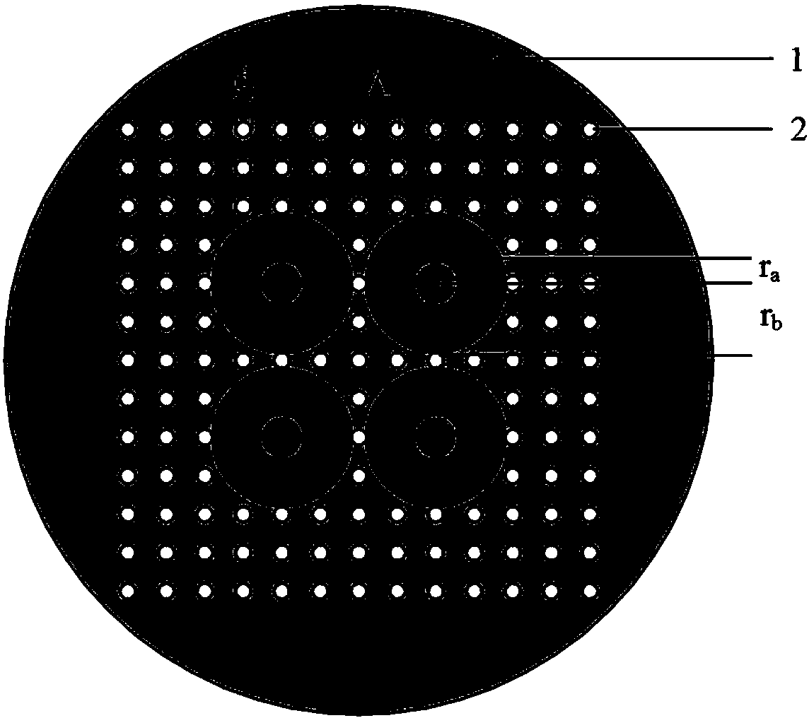
[0019] exist figure 1 In the cross-sectional view of the photonic crystal fiber shown in Embodiment 1 of the present invention, the fiber is mainly composed of a core and a cladding. Wherein, there are 13'13-3'3'4=133 air holes 2 in a uniform square array in the optical fiber cladding 1, the diameter of the air holes is d=4 μm, and the distance between two holes Λ=10 μm. Four groups of units lacking 3'3 air holes constitute the core, and the four cores are symmetrically distributed on the diagonals of the four quadrants. Each fiber core includes an inner core 3 and a doped annular region 4, wherein the inner core is made of quartz with a radius of ra=6μm, and the highly doped annular region wrapped outside the inner core is quartz-based doped with a molar percentage It is 4.25% germanium dioxide, which makes its refractive index 1.4504, which is slightly higher than the refractive index of 1.45 of the quartz inner core. The thickness of the highly doped annular region is the...
Embodiment 2
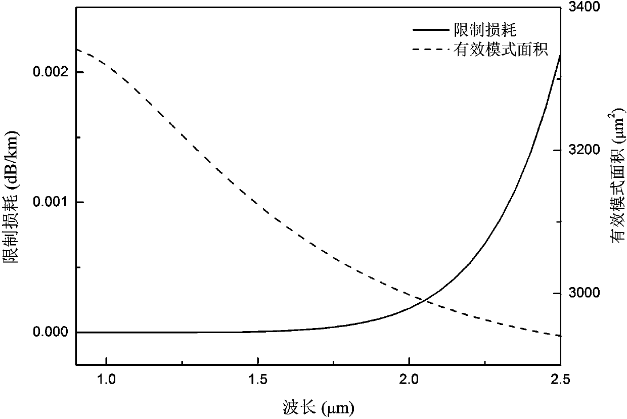
[0023] Example 2 of the present invention is basically the same as Example 1, except that the molar percentage of doped germanium dioxide is reduced to 4.11% (corresponding to a refractive index of 1.4502), and the relationship between the effective mode area and confinement loss with wavelength is as follows Figure 4 shown. It can be seen from the figure that, compared with the fiber in Example 1, the optical fiber has a smaller effective mode area and higher confinement loss. At λ=1.55 μm, its effective mode area is 2934 μm 2 , the limiting loss is 1.42′10 -4 dB / km.
Embodiment 3
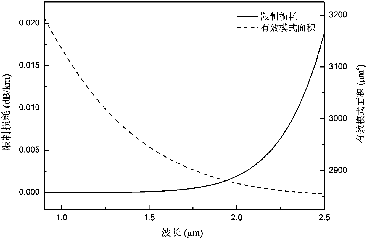
[0025] Example 3 of the present invention is basically the same as Example 1, except that the molar percentage of doped germanium dioxide is increased to 4.38% (corresponding to a refractive index of 1.4506), and the relationship between the effective mode area and confinement loss with wavelength is as follows Figure 5 shown. It can be seen from the figure that the optical fiber has a larger effective mode area and lower confinement loss than the optical fiber of the first embodiment. At λ=1.55 μm, its effective mode area is 3244 μm 2 , the limiting loss is 1.32′10 -6 dB / km.
PUM
| Property | Measurement | Unit |
|---|---|---|
| radius | aaaaa | aaaaa |
| radius | aaaaa | aaaaa |
| refractive index | aaaaa | aaaaa |
Abstract
Description
Claims
Application Information
 - R&D
- Intellectual Property
- Life Sciences
- Materials
- Tech Scout
- Unparalleled Data Quality
- Higher Quality Content
- 60% Fewer Hallucinations
Browse by: Latest US Patents, China's latest patents, Technical Efficacy Thesaurus, Application Domain, Technology Topic, Popular Technical Reports.
© 2025 PatSnap. All rights reserved.Legal|Privacy policy|Modern Slavery Act Transparency Statement|Sitemap|About US| Contact US: help@patsnap.com


