Device and method for using two-stage jet absorption heat pump to improve thermal cycle efficiency

A thermodynamic cycle and heat pump technology, applied in heat pumps, steam engine devices, preheating, etc., can solve problems such as poor thermal cycle efficiency, and achieve the effect of simple structure, high conversion rate, and fewer circulating pumps

Active Publication Date: 2012-12-05
河北蓝保能源科技集团有限公司
View PDF6 Cites 7 Cited by
  • Summary
  • Abstract
  • Description
  • Claims
  • Application Information

AI Technical Summary

Problems solved by technology

[0005] CN102620478A disclosed on August 1, 2012 a method and device for improving thermal cycle efficiency in a thermal power plant or a nuclear power plant, the defect of which is that the thermal cycle efficiency is not good

Method used


Image

  • Device and method for using two-stage jet absorption heat pump to improve thermal cycle efficiency
  • Device and method for using two-stage jet absorption heat pump to improve thermal cycle efficiency

Examples


Embodiment 1

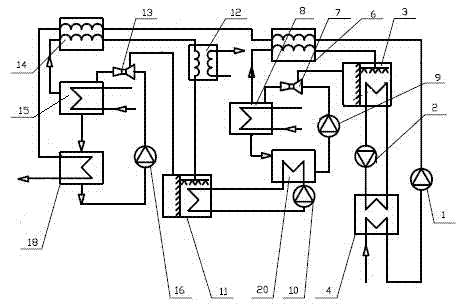
[0030] refer to figure 1 In this embodiment, the device for improving thermal cycle efficiency using a two-stage jet absorption heat pump includes a condenser 4, an evaporator I3, a condenser I6, a jet pump I7, a generator I8, and an absorber I20. The condenser 4 One side is connected to the evaporator I3 through the pipeline provided with the refrigerant water circulation pump I2, and the other side is connected to the condenser I6 through the pipeline provided with the condensate water circulation pump 1, and the evaporator I3 is connected to the condenser through the pipeline respectively. I6, the injection end of the jet pump I7 is connected, the condenser I6 is connected to the generator I8 through a pipeline, and the generator I8 is connected to the absorber I20 and the ejection outlet end of the jet pump I7 through a pipeline respectively, and the The absorber I20 is connected to the inlet end of the jet pump I7 through the pipeline provided with the jet absorption circ...

Embodiment 2

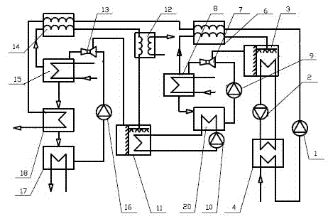
[0037] refer to figure 2 The difference between the device for improving thermal cycle efficiency by adopting two-stage jet absorption heat pumps in this embodiment and embodiment 1 is that a heat exchanger I17 is provided between the absorber II18 and the jet absorption circulation pump II16, and the heat exchange Device I17 is connected to the end of the user through a circulating pump and pipeline.

[0038] Of course, the heat exchanger I17 can also be connected to a cooling device through a circulating pump and pipelines, or connected to a next-stage heat pump circulation system, so as to provide a heat source for the next-stage heat pump.

[0039] The difference between the method of this embodiment and the embodiment 1 is that the concentrated absorption liquid in the absorber II18 is used as the heat source for heating. Of course, it can also be used for the needs of the drying process of enterprises.


PUM


Abstract

Disclosed are a device and a method for using a two-stage jet absorption heat pump to improve thermal cycle efficiency. The device comprises a steam condenser, a first evaporator, a first condenser, a first jet pump, a first generator, a first absorber, a second evaporator, a second condenser, a second jet pump, a second generator, a second absorber and a second heat exchanger. One side of the second evaporator is connected with the first absorber. The other side of the second evaporator is connected with an injecting end of the second jet pump and the second heat exchanger respectively through a pipeline. One side of the second condenser is connected with the second generator and the second heat exchanger respectively through a pipeline. The other side of the second condenser is connected with the second absorber and the first condenser respectively through a pipeline. The second generator is connected with a jet outlet end of the second jet pump and the second absorber respectively through a pipeline. The second absorber is connected with an inlet end of the second jet pump through a pipeline provided with a second jet absorbing cycle pump. The invention further discloses the method for using the two-stage jet absorption heat pump to improve thermal cycle efficiency. By the device and the method, thermal cycle efficiency can be better improved.

Description

technical field [0001] The invention relates to a device and method for improving thermal cycle efficiency by using a two-stage injection absorption heat pump. Background technique [0002] At present, in order to improve the thermal cycle efficiency of thermal power plants or nuclear power plants, it is generally considered from the following five aspects: adopting feedwater reheating cycle, improving steam parameters, adopting intermediate reheating cycle, adopting double-phase combined cycle, and implementing combined heat and power generation. Practice has shown that the power generation efficiency of thermal power plants is about 39%, and the power generation efficiency of nuclear power plants is about 35%. Even if ultra-supercritical boilers are used, the power generation efficiency is difficult to break through 45%. Most of the heat energy is lost to the air around the power plant or in rivers, seas and lakes, which not only causes waste of heat energy, increases oper...

Claims


Application Information

Patent Timeline
Patent Type & Authority Applications(China)
IPC IPC(8): F22D11/00F25B30/04F01K17/06
CPCY02E20/14
Inventor 刘小江刘赟
Owner 河北蓝保能源科技集团有限公司
Why Eureka
Try Eureka