Eureka AIR delivers breakthrough ideas for toughest innovation challenges, trusted by R&D personnel around the world.

Adaptive control method for repeater-station output signals, and device and system of adaptive control method

An adaptive control and output signal technology, applied in the field of communication, can solve problems such as limited precision and real-time performance, inability to eliminate isolation constraints, and not paying attention to the quality of signals transmitted by repeaters

Active Publication Date:
View PDF5 Cites 23 Cited by
  • Summary
  • Abstract
  • Description
  • Claims
  • Application Information

AI Technical Summary

Problems solved by technology

[0009] However, this technique has certain limitations: it is only used as a way to speed up the convergence of the channel estimator, so it belongs to an optimization of the echo cancellation technique
[0013] Although this technology takes into account the automatic detection of the antenna isolation and the adaptive adjustment of the gain of the repeater, it also does not introduce echo cancellation technology, so it can only be regarded as an isolation integrated in the repeater The automatic measurement method of the degree is equivalent to using the adaptive gain according to the timing measurement results, and the adjustment replaces the manual adjustment in the traditional sense, which cannot eliminate the constraint of the isolation degree on the repeater; secondly, the work of this technology requires additional equipment (standard signal source), and when it is necessary to occupy an in-band idle channel to send a reference signal, at the same time, the pre-adaptation stage of its reference level generation also needs to close the normal working channel to obtain the level measurement results, so the measurement accuracy and real-time tracking are relatively limited; finally, like all other technologies, this invention is not concerned with the quality of the signal transmitted by the repeater

Method used


Image

  • Adaptive control method for repeater-station output signals, and device and system of adaptive control method
  • Adaptive control method for repeater-station output signals, and device and system of adaptive control method
  • Adaptive control method for repeater-station output signals, and device and system of adaptive control method

Examples


Embodiment

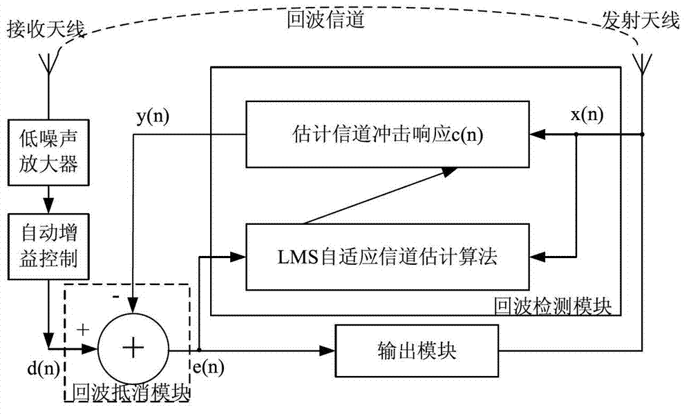
[0060] like figure 1 As shown, this embodiment relates to a repeater with adaptive signal adjustment, including: receiving antennas connected in sequence, low noise amplifiers, automatic gain control, echo cancellation system and adaptive control module.

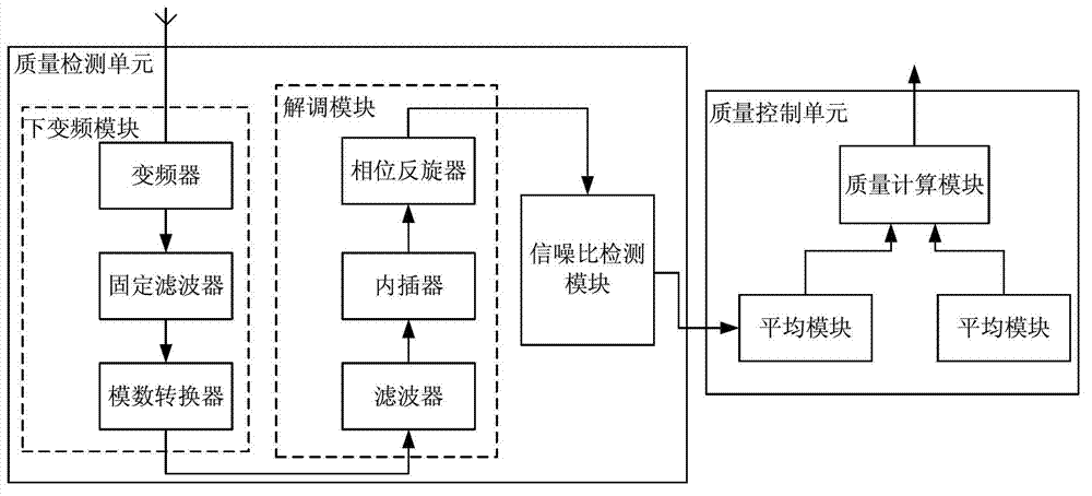
[0061] The adaptive control module includes: an output module containing a transmitting antenna and a signal quality detection module connected thereto, wherein: the output module respectively receives useful signals output by the echo cancellation system after echo detection and echo cancellation And the output power control variable of the signal quality detection module, after power amplification and band-pass filtering, the signals are respectively output to the transmitting antenna to complete the output of radio frequency signals, and at the same time lead back to the input terminal of the signal quality detection module.

[0062] The signal quality detection module includes: a quality detection unit and a quality cont...


PUM


Abstract

Disclosed are an adaptive control method for repeater-station output signals, and a device and a system of the adaptive control method. The adaptive control method is achieved in a manner that, the quality of the repeater-station output signals is detected, a signal-quality characterization value is compared with a signal-quality threshold after signal-quality calculation, and the dynamic power control is carried out based on the comparison result. According to the invention, echo cancellation technology, signal-quality monitoring and adaptive power regulation are combined so as to ensure the maximal output power while the signal quality is higher than the signal-quality threshold, and the self-excitation of the repeater station is effectively prevented, thereby helping the widening of the coverage area of the repeater station, improving the coverage effect of the repeater station, and eventually enabling self-consistent operations between the repeater stations in the point adding network.

Description

technical field [0001] The present invention relates to a method and a device in the technical field of communication, in particular to an adaptive control method for outputting signals of a repeater and its device and system. Background technique [0002] With the rapid development of modern information technology, a new generation of mobile communication technology, as well as digital TV and mobile TV terrestrial broadcasting technology, all have higher requirements for wireless signal coverage. Mobile communication networks and broadcasting networks often encounter many difficulties in order to achieve good signal coverage. In large and medium-sized cities, there are some reasons such as high-rise buildings, geographical environment, mountain occlusion, lake and sea reflection, etc., which often cause some coverage weak signal areas and blind areas. Due to the characteristics of low investment, simple structure and convenient installation, repeaters are widely used in so...

Claims


Application Information

Patent Timeline
Patent Type & Authority Applications(China)
IPC IPC(8): H04W52/04H04W52/34H04B7/155H04M9/08
CPCH04B7/15535H04B7/14
Inventor 宋伯炜李文华夏劲松赵振华范莹莹
Why Eureka
Eureka Blog
Learn More