
Precise stroke adjusting device

A stroke adjustment and precision technology, applied in the direction of presses, manufacturing tools, etc., can solve the problems of inability to realize precise adjustment of forming machines, subject to subjective factors, and large stroke adjustment range

Inactive Publication Date: 2012-11-21
BEIJING RES INST OF MECHANICAL&ELECTRICAL TECH
View PDF7 Cites 2 Cited by
  • Summary
  • Abstract
  • Description
  • Claims
  • Application Information

AI Technical Summary

Problems solved by technology

[0002] At present, most of the stroke adjustment of the forming machine adopts the method of manual operation adjustment. The stroke adjustment range is large and cannot be adjusted in real time. Due to subjective factors, the adjustment accuracy is low, and it cannot meet the high-precision requirements of the stamping mold clamping height, such as stamping heat dissipation. When using the heat sink of the heat sink, the precision of the height of the heat sink is very high. When the equipment is affected by the temperature during the working process, in order to ensure the high precision requirements of the height of the heat sink, it is necessary to fine-tune the mold clamping height in real time. However, the current adjustment method It is impossible to realize the precise adjustment of the stroke of this type of forming machine

Method used


Image

  • Precise stroke adjusting device
  • Precise stroke adjusting device
  • Precise stroke adjusting device

Examples


specific Embodiment approach

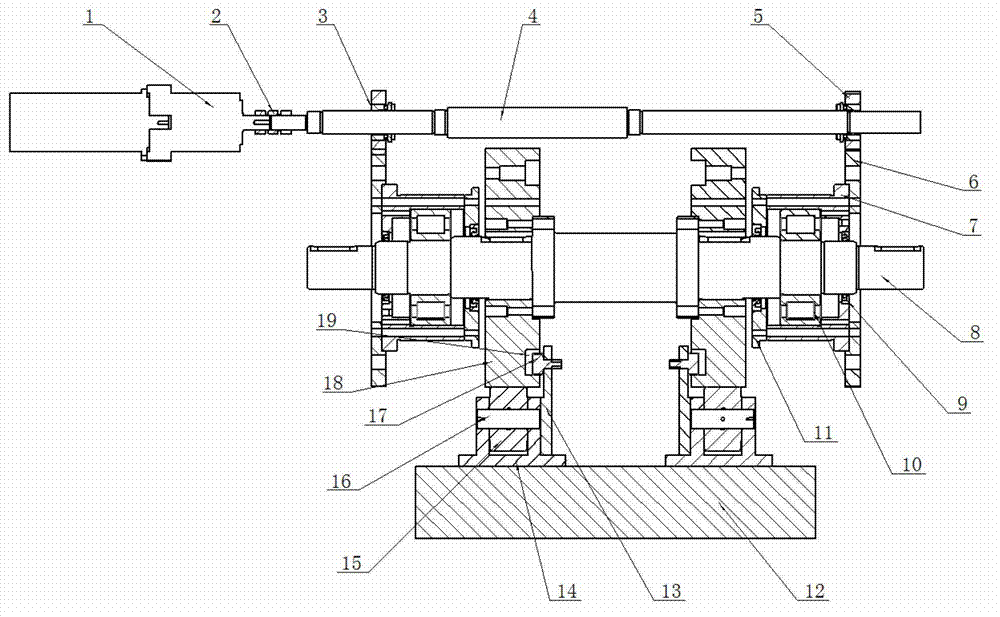
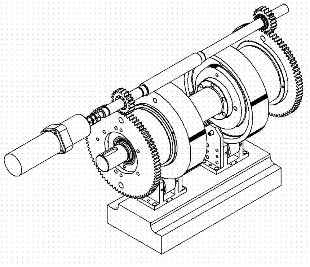
[0015] The precise stroke adjustment device of the present invention, its preferred embodiment is:

[0016] Including pinion shaft system, upper shaft system and roller slider system;

[0017] The pinion shaft system includes a servo motor and a pinion shaft connected to each other, and a pinion is fixed on the pinion shaft;

[0018] The upper shaft system includes an upper shaft, on which a cam is fixed, and an eccentric sleeve is installed through a bearing. The eccentric sleeve is fixed with a bull gear, and the bull gear meshes with the pinion gear. The end face is provided with an annular groove;

[0019] The roller slider system includes an upper mold slider, a roller bracket is fixed on the upper mold slider, a sheave bracket is fixed on the roller bracket, a roller is installed on the roller bracket, and a A cam follower, the outer edge of the cam engages with the outer edge of the roller, the cam follower engages with the annular groove.

[0020] An eccentric sleev...


PUM


Abstract

The invention discloses a precise stroke adjusting device. The precise stroke adjusting device comprises a pinion shaft system, an upper shaft system and a roller sliding block system, wherein the pinion shaft system comprises a servo motor and a pinion shaft which are connected with each other; a pinion is fixed on the pinion shaft; the upper shaft system comprises an upper shaft; a cam is fixed on the upper shaft; the upper shaft is provided with an eccentric bushing by a bearing; a large gear is fixed at the eccentric bushing; the large gear and the pinion are meshed; the end face of the cam is provided with an annular tank; the roller sliding block system comprises an upper mold sliding block; a roller support is fixed on the upper mold sliding block; a sheave support is fixed on the roller bracket; the roller bracket is provided with a roller; the sheave support is provided with a cam follower; the outer edge of the cam and the outer edge of the roller are meshed; and the cam follower and the annular tank are meshed. During the transmission process of the large gear and the pinion, the eccentric bushing performs a rotating motion following with the large gear; the upper mold sliding block is driven by the upper shaft, the cam and the follower to move up and down, so that the precise adjustment of the stroke of a forming machine is achieved.

Description

technical field [0001] The invention relates to a stroke adjustment device of a forming machine, in particular to a precision stroke adjustment device. Background technique [0002] At present, most of the stroke adjustment of the forming machine adopts the method of manual operation adjustment. The stroke adjustment range is large and cannot be adjusted in real time. Due to subjective factors, the adjustment accuracy is low, and it cannot meet the high-precision requirements of the stamping mold clamping height, such as stamping heat dissipation. When using the heat sink of the heat sink, the precision of the height of the heat sink is very high. When the equipment is affected by the temperature during the working process, in order to ensure the high precision requirements of the height of the heat sink, it is necessary to fine-tune the mold clamping height in real time. However, the current adjustment method All cannot realize the precise adjustment of this type of forming...

Claims


Application Information

Patent Timeline
IPC IPC(8): B30B15/02
Inventor 陆文林冯泽舟王勇杨继萱孙梦莹
Owner BEIJING RES INST OF MECHANICAL&ELECTRICAL TECH
Learn More