
A folded object image splicing grating pulse compressor and splicing state diagnosis system

A state diagnosis and pulse compression technology, applied in diffraction gratings, optics, instruments, etc., can solve the problems of large space consumption of compressors, complex splicing state diagnosis systems, and large splicing deviations of splicing gratings, etc. The effect of small space and simplified system structure

Active Publication Date: 2015-12-23
中国工程物理研究院上海激光等离子体研究所
View PDF4 Cites 0 Cited by
  • Summary
  • Abstract
  • Description
  • Claims
  • Application Information

AI Technical Summary

Problems solved by technology

The compressor and monitoring system designed above have the following technical deficiencies: 1. There are too many splicing deviations of the splicing grating inside the compressor, a total of twenty-four; 2. The splicing status diagnosis system is too complicated; 3. The compressor consumes a lot of space

Method used


Image

  • A folded object image splicing grating pulse compressor and splicing state diagnosis system
  • A folded object image splicing grating pulse compressor and splicing state diagnosis system
  • A folded object image splicing grating pulse compressor and splicing state diagnosis system

Examples


Embodiment Construction

[0035] Below we will further elaborate on the folded object image splicing grating pulse compressor and the splicing state diagnosis system of the present invention in combination with the accompanying drawings and specific embodiments, in order to understand the structural composition and work flow of the present invention more clearly , but it cannot be used to limit the protection scope of the patent of the present invention.

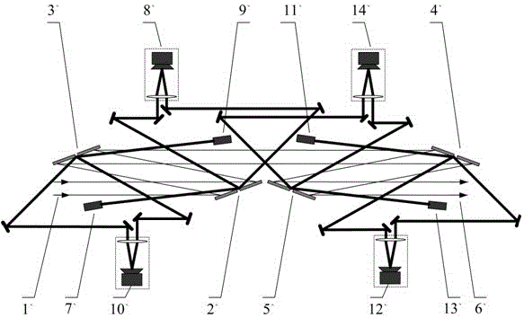
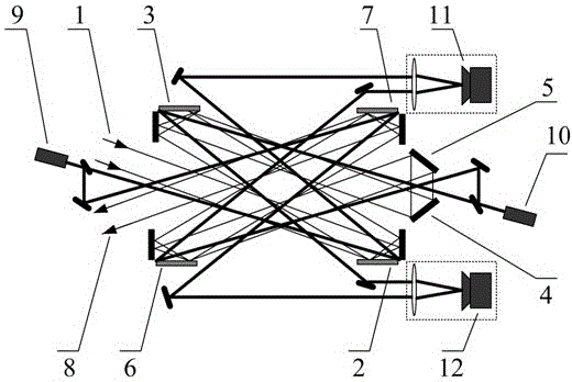
[0036] The structure of the present invention can be formed by image 3It is clearly seen that the folded object-image spliced ​​grating pulse compressor of the present invention includes four groups of spliced ​​gratings and two folded mirrors. The four groups of mosaic gratings are the first group of mosaic gratings 2 , the second group of mosaic gratings 3 , the third group of mosaic gratings 6 and the fourth group of mosaic gratings 7 . Each group of spliced ​​gratings is composed of an internal grating and an internal reflector at right angles ...


PUM


Abstract

The invention relates to a folded object-image splicing grating pulse compressor and a splicing state diagnosis system. The folded object-image splicing grating pulse compressor includes four sets of splicing gratings and two folding mirrors. Among the four sets of splicing gratings The first group of mosaic gratings is parallel to the second group of mosaic gratings, the third group of mosaic gratings is parallel to the fourth group of mosaic gratings, and the two pairs of parallel mosaic gratings are symmetrically distributed up and down; the splicing state diagnosis system includes two monitoring light sources and two observation devices , each monitoring light source emits a light beam and is divided into two monitoring beams, and the four monitoring beams respectively pass through four splicing positions and are received by corresponding observation devices to form diffractive light focal spots. The compressor and diagnosis system of the invention reduce the volume of the compressor, reduce the splicing deviation of the spliced ​​grating, and simplify the splicing state diagnosis system.

Description

technical field [0001] The invention relates to a laser device, in particular to a compressor for a chirped pulse amplifying laser, and a splicing state diagnosis system for the compressor. Background technique [0002] In the field of high-energy lasers, chirped pulse amplification technology has created conditions for the generation of ultra-intense and ultra-short lasers. The technical route of chirped pulse amplification is: the ultra-short seed pulse introduces positive dispersion through the stretcher and expands it into a long chirped pulse in the time domain, amplifies the power of the amplifier, and then introduces negative dispersion through the compressor to compress and restore the long chirped pulse for ultrashort pulses. The compressor is composed of a diffraction grating. The working principle is that when the positive chirped pulse passes through the parallel grating, different spectral components experience different optical paths, and the dispersion conjug...

Claims


Application Information

Patent Timeline
Patent Type & Authority Patents(China)
IPC IPC(8): G02F1/35G02B7/182G02B7/00G02B5/18G01M11/02
Inventor 李朝阳戴亚平王韬徐光马伟新朱俭
Owner 中国工程物理研究院上海激光等离子体研究所
Learn More