Communication device and communication method
A communication device and wireless communication technology, applied in telephone communication, collaborative work device, antenna support/installation device, etc., can solve the problem of not being able to guide the user to the position of the antenna, and achieve the effect of easy alignment
- Summary
- Abstract
- Description
- Claims
- Application Information
AI Technical Summary
Problems solved by technology
Method used
Image
Examples
Embodiment approach 1
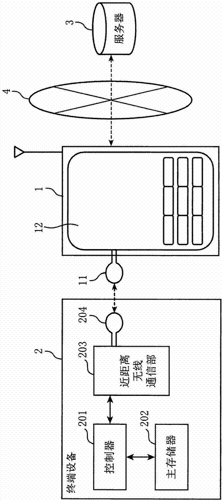
[0033] In Embodiment 1, for example, a portable device equipped with an RFID reader / writer is brought close to a terminal device equipped with RFID, terminal device information including information indicating the terminal device such as an ID is read out from the terminal device, and the portable device itself The information is sent to the server in addition to the terminal device information read by the portable device. Thereby, for example, the terminal device information and the mobile device information can be associated and registered in the database of the server.
[0034] Conventionally, user registration operations such as registering an e-mail address with a server and registering a manufacturing number have been performed by direct input from the user. For this reason, due to the complexity of the input processing job, the number of terminal devices registered with the server is not large. On the other hand, in the mobile device according to Embodiment 1, informat...
Embodiment approach 2
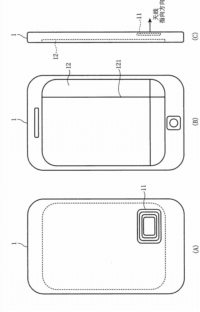
[0086] Next, a communication system in Embodiment 2 of the present invention will be described. In Embodiment 2, a guide pattern image having the same shape as the guide pattern indicating the position of the loop antenna mounted on the terminal device is displayed at the position of the loop antenna mounted on the mobile device.
[0087] Figure 7 It is a figure showing the internal structure of the mobile device in Embodiment 2 of this invention. In addition, since the configuration of the communication system in Embodiment 2 of the present invention is the same as the configuration of the communication system in Embodiment 1, description thereof will be omitted.
[0088] Figure 7 The illustrated portable device 1 includes a loop antenna 11, a display unit 12, a system control unit 13, a storage unit 14, a short-range wireless communication unit 15, an operation unit 16, a guide display control unit 17, a posture detection unit 18, and a mobile network communication unit....
Embodiment approach 3
[0119] Next, a communication system in Embodiment 3 of the present invention will be described. In Embodiment 3, the position of the loop antenna is superimposed on the captured image of the pointing direction of the loop antenna and displayed.
[0120] Figure 12 It is a figure showing the internal structure of the mobile device in Embodiment 3 of this invention. In addition, the configuration of the communication system in Embodiment 3 of the present invention is the same as the configuration of the communication system in Embodiment 1, and thus description thereof will be omitted.
[0121] Figure 12 The illustrated portable device 1 includes a loop antenna 11, a display unit 12, a system control unit 13, a storage unit 14, a short-range wireless communication unit 15, an operation unit 16, a guidance display control unit 17, a posture detection unit 18, and a mobile network communication unit. 19. An antenna 20 , an image acquisition unit 21 and a pattern recognition un...
PUM
 Abstract
Description
Claims
Application Information
 - R&D
- Intellectual Property
- Life Sciences
- Materials
- Tech Scout
- Unparalleled Data Quality
- Higher Quality Content
- 60% Fewer Hallucinations
Browse by: Latest US Patents, China's latest patents, Technical Efficacy Thesaurus, Application Domain, Technology Topic, Popular Technical Reports.
© 2025 PatSnap. All rights reserved.Legal|Privacy policy|Modern Slavery Act Transparency Statement|Sitemap|About US| Contact US: help@patsnap.com


