
Hartman wave front detector with aperture alignment function

A detector and photodetector technology, applied in instruments, measuring devices, scientific instruments, etc., can solve the problems of deviation of measurement results, inability to precisely control, access, etc., and achieve the effect of precise alignment

Active Publication Date: 2012-11-14
CHANGCHUN INST OF OPTICS FINE MECHANICS & PHYSICS CHINESE ACAD OF SCI
View PDF4 Cites 5 Cited by
  • Summary
  • Abstract
  • Description
  • Claims
  • Application Information

AI Technical Summary

Problems solved by technology

However, whether the incident beam can completely cover the designed microlens array, that is, whether the incident beam aperture can be aligned with the clear aperture of the Hartmann wavefront detector cannot be precisely controlled.
In order to increase the data readout speed of the Hartmann wavefront detector, the focused light spot behind the microlens should occupy as few photodetector pixels as possible, and even cover only 2×2 pixels, so the light spot After zooming in to the size that the pixels can display, the shape of the "dot" can no longer be seen, and the alignment relationship between the microlens array and the aperture of the system under test cannot be directly obtained from the light intensity distribution of the focused light spot
[0005] The deviation of the aperture position will cause only half or part of the light spot at the edge to enter the photodetector, which will inevitably lead to deviations in the measurement results, thereby introducing large measurement errors

Method used


Image

  • Hartman wave front detector with aperture alignment function
  • Hartman wave front detector with aperture alignment function
  • Hartman wave front detector with aperture alignment function

Examples


Embodiment Construction

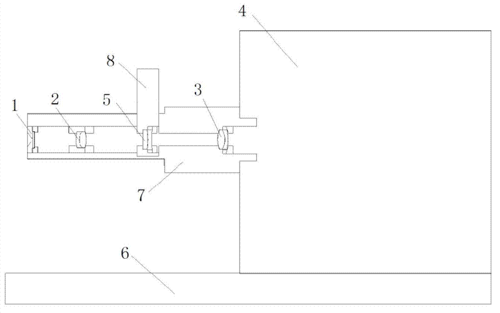
[0017] 1) The microlens array 1 is a circular plano-convex lens purchased from SUSS Company and a rectangularly arranged microlens array panel. The diameter of a single microlens is 150 μm, the radius of curvature is 3400 μm, and the focal length f 1 =4.40mm, the size of the entire panel is 10mm×10mm×1.20mm, attached to a 1.5mm aperture diaphragm, that is, the aperture D 1 =1.5mm.

[0018]2) The first lens 2, the second lens 3, and the switching concave lens 5 are double-cemented achromatic lenses, and the surface is coated with an anti-reflection coating. The diameters are 5mm, 6mm, and 5mm, and the thicknesses are 3.00mm, 3.00mm, and 2.00 mm, the focal lengths are 10.00mm, 12.80mm, -22.73mm respectively.

[0019] 3) The photodetector 4 is a high-sensitivity EMCCD (DV897 from ANDOR, UK), with a pixel count of 128×128, and a square light window of 1.9mm×1.9mm, namely the aperture D 4 =1.9mm, the number of pixels in the light window is 80×80, using 2×2 binning mode, the sampl...


PUM

PropertyMeasurementUnit
Caliberaaaaaaaaaa
Thicknessaaaaaaaaaa
Focal lengthaaaaaaaaaa

Abstract

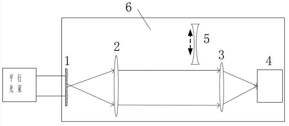
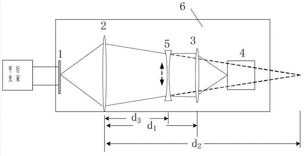
The invention provides a Hartman wave front detector with an aperture alignment function. The Hartman wave front detector is characterized by consisting of a traditional Hartman wave front detector, a switching concave lens and a micromovement table, wherein the whole device is fixedly arranged on the micromovement table; the micromovement table can perform two-dimensional translation, pitching, torsional pendulum and rotation on the section of an optical axis so as to adjust the optical axis of the Hartman detector; the switching concave lens is fixedly arranged on an insertion plate; during aperture alignment, the insertion plate is inserted into a slot of a switching lens cone, so that the switching concave lens is switched into the light path of a switching lens as shown in the figure, and thus an image of a light spot array on a photodetector is switched into a real image of a microlens array; while the morphology of the microlens array in the photodetector is monitored, the micromovement table is adjusted, until the end points of a vertical diameter and a horizontal diameter of a visual field have complete microlenses, aperture alignment is finished; and after aperture alignment is finished, the insertion plate is pulled up, so that the switching concave lens is moved out of the light path of the switching lens, so that the traditional Hartman wave front detector is recovered.

Description

technical field [0001] The invention belongs to the field of photoelectric signal detection, and relates to a Hartmann wavefront detector, an optical instrument used for wavefront shape measurement. It consists of optical components such as photodetectors, microlens arrays and lenses, specifically a Hartmann wavefront detector with aperture alignment. Background technique [0002] The Hartmann wavefront detector is a wavefront measurement device widely used in optical surface shape inspection, optical system adjustment, especially in adaptive optics technology. A traditional Hartmann wavefront detector consists of a microlens array, an adapter lens, a photodetector (usually CCD or CMOS) and data processing software. The incident light first passes through the microlens array, and then passes through the adapter lens so that the beam diameter is exactly the same as the aperture of the photodetector, enters it, forms an image, and finally reads the detection data from the pho...

Claims


Application Information

Patent Timeline
IPC IPC(8): G01J9/00G02B7/02
Inventor 宣丽穆全全曹召良胡立发彭增辉刘永刚姚丽双李大禹杨程亮夏明亮鲁兴海
Owner CHANGCHUN INST OF OPTICS FINE MECHANICS & PHYSICS CHINESE ACAD OF SCI
Learn More