Hydraulic control cycling switch

A technology for controlling circulation and switching, which is applied in wellbore/well components, earthwork drilling, wellbore flushing, etc. It can solve problems such as troublesome workover operations, waste of wellwashing fluid, and polluted oil layers, and achieves simple structure and convenient use , the effect of easy operation

Inactive Publication Date: 2012-11-14
顾明祥
View PDF0 Cites 0 Cited by
  • Summary
  • Abstract
  • Description
  • Claims
  • Application Information

AI Technical Summary

Problems solved by technology

Lost circulation not only causes a lot of waste of well cleaning fluid, but also seriously pollutes the oil reservoir, reducing the fluid production of the oil well. , Oil wells that cannot blow out spontaneously will suddenly blow out during workover operations, often causing heavy losses in human, property and material
Sometimes the formation pressure is slightly higher than the bottom hole pressure, although blowout will not occur, but the crude oil gushing out of the wellhead will bring a lot of trouble to the workover operation

Method used


Image

  • Hydraulic control cycling switch
  • Hydraulic control cycling switch

Examples


Embodiment Construction

[0015] The implementation and working process of the present invention will be described in detail below in conjunction with the accompanying drawings.

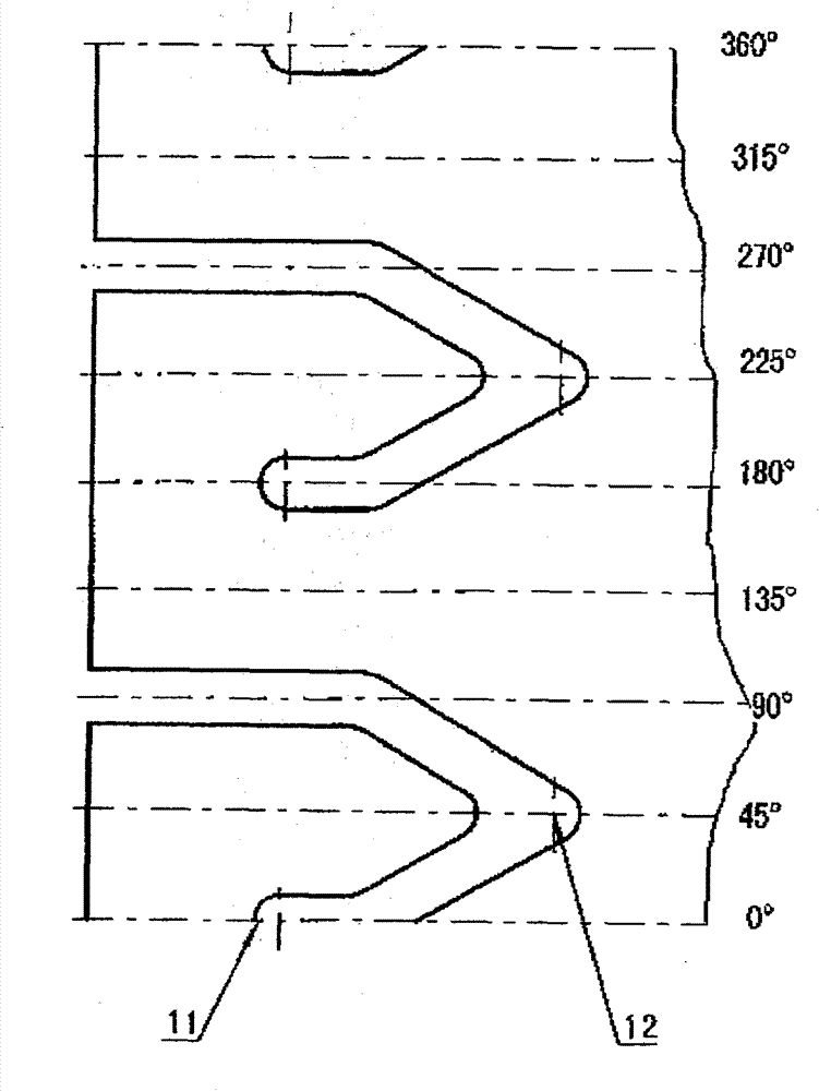
[0016] Such as figure 1 , figure 2 Shown:

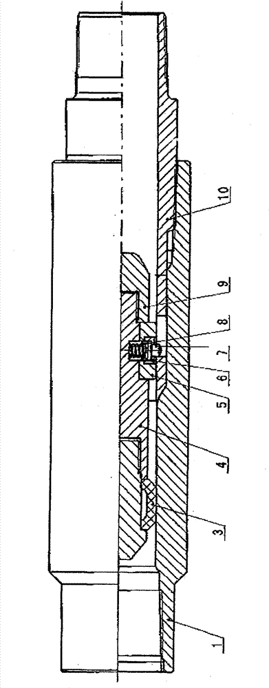
[0017] A hydraulic control cycle switch is mainly composed of an upper joint 1, an upper guide body 2, a rubber 3, a connecting body 4, a fixing ring 5, a nut 6 for the fixing ring, a track pin 7, a spring 8, a lower guide body 9, and a lower joint 10 composition.

[0018] The specific implementation is as follows:

[0019] First put the fixed ring 5 on the connecting body 6 and rotate it so that the spring holes on the two parts correspond, put the spring 8 in the spring hole and install the track pin 7, and then connect the fixed ring nut 6 to the fixed On the ring 5, the lower guide body 9 is threadedly connected to the connecting body 4, the rubber 3 is set on the outer cylindrical surface of the upper guiding body 2, and then the upper guiding body 2 and the connecting bod...


PUM


Abstract

A hydraulic control cycling switch is formed by an upper joint, an upper guiding body, a rubber sheet, a connecting body, a fixing ring, a nut for the fixing ring, track pins, springs, a lower guiding body and a lower joint. The fixing ring is firstly sleeved on the connecting body, so that spring holes on two parts correspond to each other; the springs are imbedded in the spring holes, and the track pins are arranged; the nut for the fixing ring is connected onto the fixing ring through screw threads; the lower guiding body is connected onto the connecting body through screw threads; the rubber sheet is sleeved on an outer cylindrical surface of the upper guiding body; and the upper guiding body and the connecting body are in thread connection. A group of symmetrical track slots connected with inner holes is arranged on an outer cylindrical surface of the upper end of the lower joint; the assembling units are imbedded into the inner holes of the lower joint; the track pins are hung on top dead centers of the track slots of the lower joint; and the whole part is connected and tightened with the upper joint through lower joint oil pipe threads. When being descent into a well, a tool is at an 'off' state, and when a channel of the oil well needs to be opened, an internal assembly of the tool is taken out through a hydraulic way, so that the channel is at an 'on' state.

Description

technical field [0001] The invention belongs to the field of manufacturing downhole tools used in oil exploitation, and in particular relates to a hydraulic control cycle switch. Background technique [0002] With the continuous extraction of crude oil in the oil well, the formation pressure of the oil layer continues to decrease, and the porosity of the oil layer near the oil well continues to increase. Therefore, in the well cleaning work of the workover operation, a large amount of well cleaning fluid often leaks into the oil layer. , known as well leakage in engineering. Lost circulation not only causes a lot of waste of well cleaning fluid, but also seriously pollutes the oil reservoir, reducing the fluid production of the oil well. , Oil wells that cannot spontaneously blow out originally will suddenly blow out during workover operations, often causing heavy losses in people, property and materials. Sometimes the formation pressure is slightly higher than the bottom ...

Claims


Application Information

Patent Timeline
Patent Type & Authority Applications(China)
IPC IPC(8): E21B21/10E21B34/10
Inventor 王海龙尚玉星顾明祥董乔云
Owner 顾明祥
Why Eureka
Try Eureka