Rack structure and application thereof

A gear structure and rack technology, applied in the field of deceleration transmission structure, can solve the problems of scrapped gears, easy wear, short service life of the substrate, etc., and achieve the effect of ensuring regular production, ensuring service life, and rapid assembly

Inactive Publication Date: 2017-12-08
SUZHOU IND PARK KAYMAX PRECISION ENG
View PDF6 Cites 1 Cited by
  • Summary
  • Abstract
  • Description
  • Claims
  • Application Information

AI Technical Summary

Problems solved by technology

[0002] The existing gear reduction structure is generally made of metal materials. However, due to the high cost and heavy weight of metal materials, in order to reduce costs, the transmission gears are made of plastic. However, due to the use of plastic injection molding or printing molding, the printing The tooth parts of the plastic parts that come out are extremely easy to wear, and the entire gear and its corresponding base need to be scrapped after wear, which makes the service life of the entire base short, and the replacement of the base is time-consuming and laborious, hindering the normal production of the entire production line

Method used


Image

  • Rack structure and application thereof
  • Rack structure and application thereof
  • Rack structure and application thereof

Examples


specific Embodiment 5

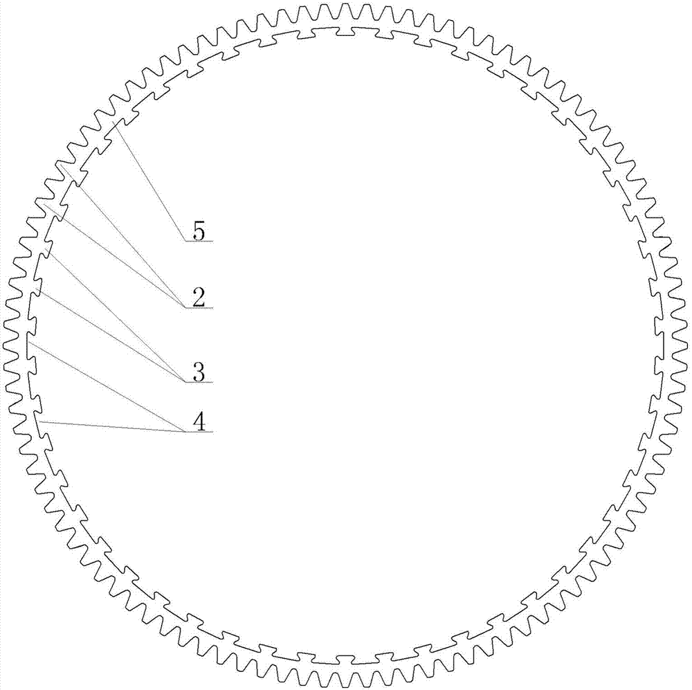
[0039] Specific embodiment five, see Figure 5 : When the rack structure of the arc carrier is not provided with the first air hole structure 7, the outer ring surface of the rack body 8 is covered with a positioning groove 9 corresponding to the radian, and the protrusion 3 and the positioning groove 9 of the rack body 8 are embedded tightly matched arrangement.

specific Embodiment 6

[0040] Concrete embodiment six, see Image 6 : When the rack structure of the arc carrier is provided with the first air hole structure 7, the outer ring surface of the rack body 8 is covered with a positioning groove 9 corresponding to the radian, and the embedding protrusion 3 and the positioning groove 9 of the rack body 8 Closely matched arrangement.

specific Embodiment 7

[0041] Specific embodiment seven, see Figure 7 : When the rack structure is not provided with the first air hole structure, the inner ring part of the positioning groove of the rack body 8 is provided with a plurality of mutually discontinuous second air hole structures 10 along the circumferential direction, and the second air hole structures 10 run through the rack body Arranged in the width direction of the rack body 8, the outer ring surface of the rack body 8 is covered with a positioning groove 9 corresponding to the radian, and the embedded protrusion 3 and the positioning groove 9 of the rack body 8 are arranged in close fit;

[0042] The second pore structure 10 is in the shape of a circle, a circle, a fan, an arc, a rectangle or a rectangle;

[0043] The overall radial compression of the second pore structure 10 is 0.1mm˜0.3mm.

[0044] In the specific embodiment, the overall radial compression of the first air hole structure 6 and the second air hole structure 10 ...


PUM


Abstract

The invention provides a rack structure. The rack structure can be directly and fixedly mounted on a corresponding matrix, once the rack structure is worn, a rack can be directly changed, normal production of a production line is ensured, and the service life of the whole matrix is also ensured. The rack structure comprises an arc carrier, wherein outwards protruded gear structures are uniformly distributed on the outer peripheral surface of the arc carrier; the gear structures are uniformly arranged in the radian direction of the outer peripheral surface of the arc carrier; inwards protruded embedding projections are uniformly distributed on the inner peripheral surface of the arc carrier; the embedding projections are uniformly arranged in the radian direction of the inner peripheral surface of the arc carrier; and a space interval is arranged between each two adjacent embedding projections.

Description

technical field [0001] The invention relates to the technical field of reduction transmission structures, in particular a rack structure, and the invention also provides an application of the rack structure. Background technique [0002] The existing gear reduction structure is generally made of metal materials. However, due to the high cost and heavy weight of metal materials, in order to reduce costs, the transmission gears are made of plastic. However, due to the use of plastic injection molding or printing, the printing The teeth of the plastic parts are easily worn out, and the entire gear and its corresponding base need to be scrapped after wear, which makes the service life of the entire base short, and the replacement of the base is time-consuming and laborious, hindering the normal production of the entire production line. Contents of the invention [0003] In view of the above problems, the present invention provides a rack structure, which can be directly fixed ...

Claims


Application Information

Patent Timeline
Patent Type & Authority Applications(China)
IPC IPC(8): F16H55/26F16H55/17F16H55/12
CPCF16H55/12F16H55/17F16H55/26B29L2015/003F16H19/04F16H55/06F16H2055/065
Inventor 蒋剑
Owner SUZHOU IND PARK KAYMAX PRECISION ENG
Why Eureka
Try Eureka