Manipulator structure with demountable rack

A technology of manipulator and gear structure, applied in the direction of manipulators, program control manipulators, mechanical equipment, etc., can solve the problems of easy wear, high cost of metal materials, short service life of manipulators, etc., and achieve the effect of ensuring the service life

Pending Publication Date: 2017-11-24
SUZHOU ARTIARM ROBOT CO LTD
View PDF4 Cites 2 Cited by
  • Summary
  • Abstract
  • Description
  • Claims
  • Application Information

AI Technical Summary

Problems solved by technology

[0002] The existing gear reduction structure is generally made of metal materials. However, due to the high cost and heavy weight of metal materials, in order to reduce costs, the transmission gear of the manipulator is made of plastic. However, due to the use of plastic injection molding or printing molding, The tooth parts of the printed plastic parts are very easy to wear, and the entire manipulator needs to be scrapped after wear, which makes the service life of the manipulator short, and the replacement of the manipulator is time-consuming and laborious, hindering the normal production of the entire production line

Method used


Image

  • Manipulator structure with demountable rack
  • Manipulator structure with demountable rack
  • Manipulator structure with demountable rack

Examples


specific Embodiment 1

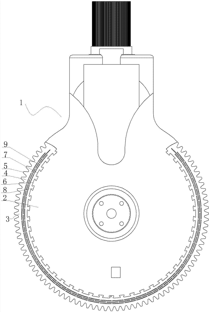
[0036] Specific embodiment one, see figure 1 : The inner peripheral surface of the arc carrier 4 is evenly distributed with inwardly convex embedded protrusions 6, and the embedded protrusions 6 are evenly arranged along the arc direction of the inner peripheral surface of the arc carrier 4, and there are 6 adjacent embedded protrusions There is an interval space 7, and the outer peripheral surface of the gear body 2 is provided with a positioning groove 8 compatible with the embedded protrusion 6, and the embedded protrusion 6 on the rack structure 5 is positioned and embedded in the corresponding positioning groove 8 , There is a tight fit between the embedding protrusion 6 and the positioning groove 8 .

specific Embodiment 2

[0037] Specific embodiment two, see figure 2 : The inner peripheral surface of the arc carrier 4 is evenly distributed with inwardly convex embedded protrusions 6, and the embedded protrusions 6 are evenly arranged along the arc direction of the inner peripheral surface of the arc carrier 4, and there are 6 adjacent embedded protrusions There is an interval space 7, and the outer peripheral surface of the gear body 2 is provided with a positioning groove 8 compatible with the embedded protrusion 6, and the embedded protrusion 6 on the rack structure 5 is positioned and embedded in the corresponding positioning groove 8 In the radial thickness direction of the arc carrier 4 or the intermediate base body, a plurality of discontinuous first air hole structures 9 are arranged along the circumferential direction.

specific Embodiment 3

[0038] Specific embodiment three, see image 3 : The inner peripheral surface of the arc carrier 4 is evenly distributed with inwardly convex embedded protrusions 6, and the embedded protrusions 6 are evenly arranged along the arc direction of the inner peripheral surface of the arc carrier 4, and there are 6 adjacent embedded protrusions There is an interval space 7, and the outer peripheral surface of the gear body 2 is provided with a positioning groove 8 compatible with the embedded protrusion 6, and the embedded protrusion 6 on the rack structure 5 is positioned and embedded in the corresponding positioning groove 8 The inner ring part of the positioning groove 8 of the rack body 2 is provided with a plurality of mutually discontinuous second air hole structures 10 along the ring direction.


PUM


Abstract

The invention provides a manipulator structure with a demountable rack. The rack is demountably mounted on a gear body of a manipulator and can be directly replaced once being worn, and accordingly normal production of a production line is guaranteed, and the service life of the manipulator is guaranteed. The manipulator structure comprises a manipulator body with a gear structure, the gear structure comprises a gear body and a rack structure, the gear body and the manipulator body form an integral structure, the rack structure is an arc carrier with outward-convex tooth structures uniformly distributed on the outer periphery, the tooth structures are uniformly distributed along the outer peripheral arc direction of the arc carrier, inward-convex embedded projections are uniformly distributed on the inner periphery of the arc carrier along the inner peripheral arc direction of the arc carrier, and an interval space is reserved between every two adjacent embedded projections.

Description

technical field [0001] The invention relates to the technical field of deceleration transmission structures, in particular to a detachable rack manipulator structure. Background technique [0002] The existing gear reduction structure is generally made of metal materials. However, due to the high cost and heavy weight of metal materials, in order to reduce costs, the transmission gear of the manipulator is made of plastic. However, due to the use of plastic injection molding or printing molding, The teeth of the printed plastic parts are very easy to wear, and the entire manipulator needs to be scrapped after wear, which makes the service life of the manipulator short, and the replacement of the manipulator is time-consuming and laborious, hindering the normal production of the entire production line. Contents of the invention [0003] In view of the above problems, the present invention provides a manipulator structure with a detachable rack, which allows the rack to be d...

Claims


Application Information

Patent Timeline
Patent Type & Authority Applications(China)
IPC IPC(8): F16H55/17F16H55/26B25J9/00
CPCF16H55/17F16H55/26B25J9/0009F16H2055/175
Inventor 蒋剑
Owner SUZHOU ARTIARM ROBOT CO LTD
Why Eureka
Try Eureka