Coating film inspection apparatus and inspection method
A technology of inspection device and inspection method, which is applied to measurement devices, optical devices, instruments, etc., can solve the problems of uneven color, difficulty in inspection, inability to grasp the uniformity of sheets, etc., to prevent measurement errors and achieve good efficiency.
- Summary
- Abstract
- Description
- Claims
- Application Information
AI Technical Summary
Problems solved by technology
Method used
Image
Examples
no. 1 approach ]
[0081] (the whole frame)
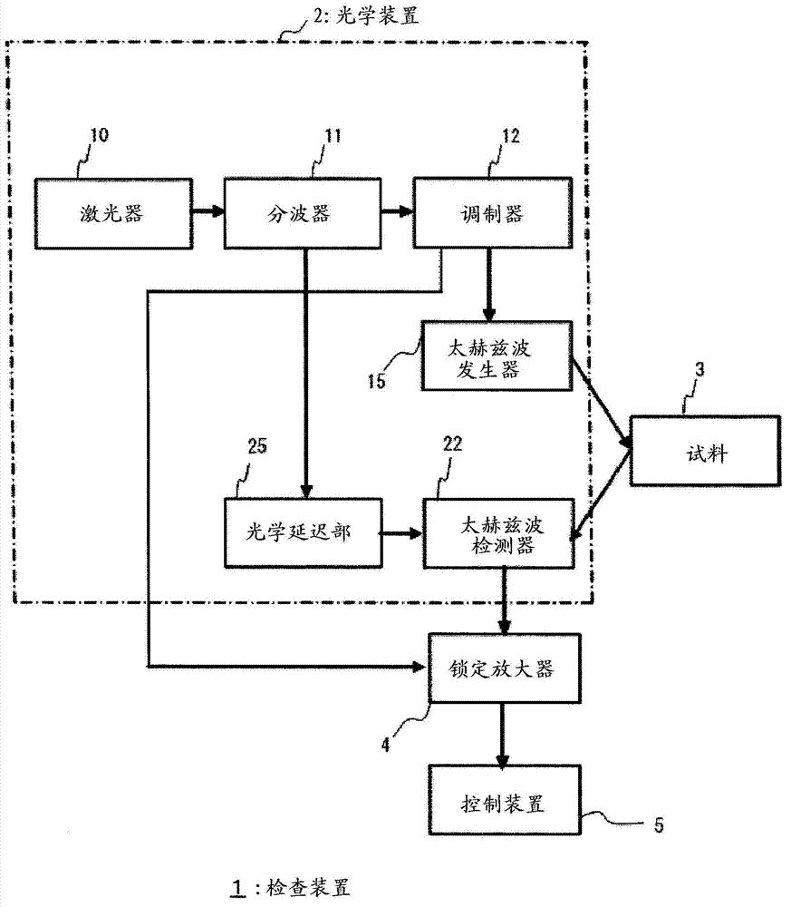
[0082] figure 1 It is a schematic structural diagram of the inspection apparatus of the coating film which concerns on 1st Embodiment of this invention.
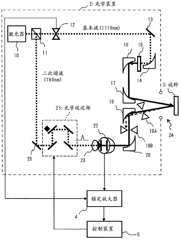
[0083] The inspection device 1 has an optical device 2 for detecting reflected waves while irradiating a sample 3 with terahertz waves, a lock-in amplifier 4 for synchronously amplifying a detection signal of the reflected waves, and a control device 5 for controlling the inspection device. The optical device 2 has a laser 10 , a demultiplexer 11 , a modulator 12 , a terahertz wave generator 15 , a terahertz detector 22 , and an optical delay unit 25 .
[0084] The laser light excited by the laser 10 is divided into a fundamental wave and a second harmonic by a wave splitter 11 . The fundamental wave is modulated into a pulse of a predetermined frequency by the modulator 12 and is incident on the terahertz wave generator 15 . The terahertz wave generated from the terahertz wave generator 15 is i...
no. 2 approach ]
[0179] Next, an inspection device according to a second embodiment of the present invention will be described. The inspection device of the present embodiment is a modified example of the first embodiment, and can measure the film thickness of the metal coating. The configuration of the inspection device of this embodiment is substantially the same as that of the first embodiment except for the peak detection process (step S56 ), so only the different configurations will be described.
[0180] Figure 22 It is a cross-sectional view of a metal coating sample. As shown in this figure, metallic coating is formed by sequentially forming a metallic coating layer and a clear coating layer on a base metal. When the coating sample is irradiated with terahertz waves, the terahertz waves are reflected at the interface where the refractive index changes. That is, the terahertz wave is reflected at the interface (1) between the air and the clear coat, the interface (2) between the cle...
no. 3 approach ]
[0197] Figure 26 , Figure 27 It is a figure for demonstrating the inspection apparatus of 3rd Embodiment of this invention. According to the inspection measures of the above-mentioned first embodiment, such as Figure 26 As shown, even in the case where there are grooves in the sample 3, the terahertz wave reaches the terahertz wave detector 22 without being scattered. Therefore, the film thickness of the bottom a of the groove can be obtained by measuring the delay of the reflected wave. However, the film thickness on the wall portions b, c not irradiated with terahertz waves cannot be measured. In the piston cylinder, the accuracy of the internal coating has a great influence on the performance of the engine, so the necessity of measuring the wall portion is high.
[0198] The inspection device of this embodiment is based on the inspection device of the first embodiment, and further includes a reflector 301 ( Figure 27 ). The reflector 301 may be a prism or the like...
PUM
| Property | Measurement | Unit |
|---|---|---|
| coating thickness | aaaaa | aaaaa |
| frequency | aaaaa | aaaaa |
| radius | aaaaa | aaaaa |
Abstract
Description
Claims
Application Information
 - Generate Ideas
- Intellectual Property
- Life Sciences
- Materials
- Tech Scout
- Unparalleled Data Quality
- Higher Quality Content
- 60% Fewer Hallucinations
Browse by: Latest US Patents, China's latest patents, Technical Efficacy Thesaurus, Application Domain, Technology Topic, Popular Technical Reports.
© 2025 PatSnap. All rights reserved.Legal|Privacy policy|Modern Slavery Act Transparency Statement|Sitemap|About US| Contact US: help@patsnap.com


