Fault injection method and device of transistor-transistor logic
A technology of transistor logic and fault injection, which is applied in the direction of logic circuit coupling/interface, logic circuit connection/interface layout, etc. using field effect transistors. It can solve the problems of different logic voltage thresholds and inability to connect directly, and achieve flexible operation.
- Summary
- Abstract
- Description
- Claims
- Application Information
AI Technical Summary
Problems solved by technology
Method used
Image
Examples
Embodiment 1
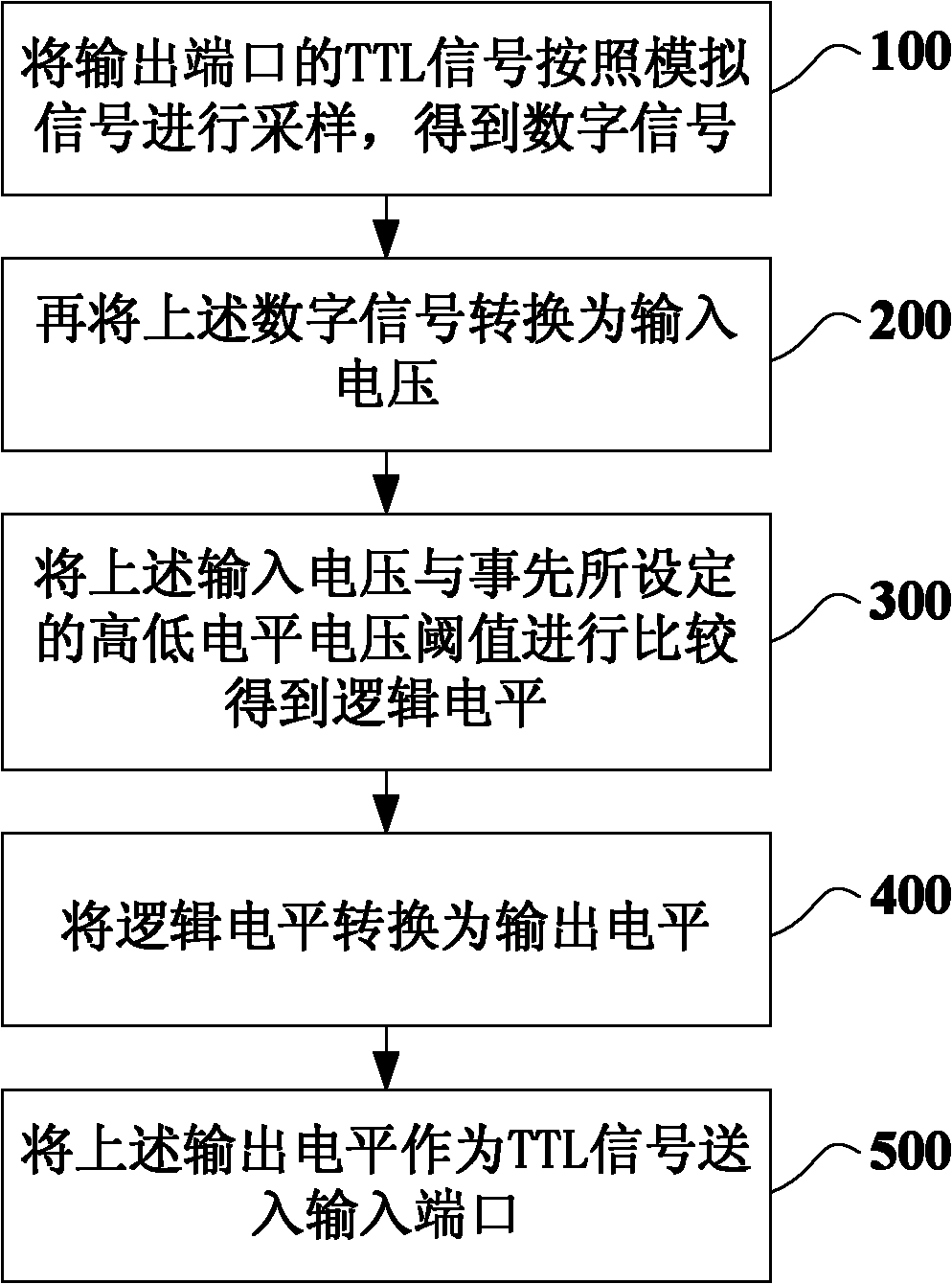
[0039] The applicant of the present invention considers that the voltage threshold level of each actual TTL / LVTTL interface can be detected by adjusting the voltage amplitude of the signal, so as to realize the interconnection between TTL / LVTTL signals of different voltages. Therefore, a TTL fault injection method is provided. Especially in this embodiment, the applicant of the present invention also changed the traditional thinking of those skilled in the art, and proposed for the first time that TTL signals are processed as analog signals. In this way, compared with simple digital signals, processing of analog signals can increase a variety of fault injection situations, making fault injection operations more flexible and repeatable. The specific fault injection process in this embodiment is as follows: figure 1 As shown, including the following steps:
[0040] Step 100, sampling the TTL signal of the output port according to the analog signal to obtain a digital signal, that i...
Embodiment 2
[0054] This embodiment proposes another fault injection method based on the idea of the above-mentioned embodiment 1. When the method obtains a TTL signal at the output port, the digital signal is obtained, but when the fault signal is injected into the input port, the analog signal is selected. Signal, the processed analog signal is injected into the input port as a TTL signal. Specifically, the process of implementing fault injection in this embodiment is as follows:
[0055] Step A: Collect the TTL signal of the output port, where the TTL signal is a digital signal;
[0056] Among them, this step can collect the TTL signal of the output port according to the prior art. For example, when the output port voltage is less than 0.8V, the collected TTL signal is 0, and when the output port voltage is above 0.8V, the collected TTL signal is 1. In some cases, you can reset the definition of TTL signal according to different application scenarios. For example, when the output port vo...
Embodiment 3
[0064] This embodiment introduces a fault injection device, which can implement the fault injection method of Embodiment 1 above. The device is like figure 2 As shown, it includes a data acquisition unit and a data processing unit. The data acquisition unit can collect the voltage signal of the output port and send the collected data to the data processing unit for processing. The data processing unit mainly adjusts the voltage amplitude of the output signal; and the data processed by the data processing unit is sent to the input port . In this way, the data at the input port is the signal after fault injection and level adjustment. The following describes the specific functions of each part.
[0065] The data acquisition unit samples the TTL signal (ie TTL signal 1) of the "output port" according to the analog signal to obtain a digital signal, and sends the digital signal to the data processing unit;
[0066] Among them, the data acquisition unit can use ADC to sample the TTL...
PUM
 Abstract
Description
Claims
Application Information
 - R&D
- Intellectual Property
- Life Sciences
- Materials
- Tech Scout
- Unparalleled Data Quality
- Higher Quality Content
- 60% Fewer Hallucinations
Browse by: Latest US Patents, China's latest patents, Technical Efficacy Thesaurus, Application Domain, Technology Topic, Popular Technical Reports.
© 2025 PatSnap. All rights reserved.Legal|Privacy policy|Modern Slavery Act Transparency Statement|Sitemap|About US| Contact US: help@patsnap.com


