Solution sampling device

A sampling device and solution technology, applied in the direction of sampling devices, etc., can solve the problems of pulse flow, air bubbles and pressure reduction, inconvenient operation, time-consuming and laborious, etc.

Inactive Publication Date: 2012-10-24
GEM JIANGSU COBALT IND CO LTD
View PDF8 Cites 4 Cited by
  • Summary
  • Abstract
  • Description
  • Claims
  • Application Information

AI Technical Summary

Problems solved by technology

[0002] In the chemical production process, especially fine chemical production, it is necessary to monitor the state of each material in a timely manner. When the material is synthesized, reacted, concentrated, acidified, leached and other processes, it is also necessary to monitor the operating parameters of the reaction system in each process, but due to The environment of the production site is complicated, and there are toxic and harmful materials such as high temperature, high pressure, strong acid, strong alkali, etc., opening sampling ports in the reaction kettle, storage tank, and pipelines to take samples manually, which is inconvenient to operate, time-consuming and laborious, and there is material liquid splashing and hurting people Security risks
[0003] The existing patent No. 200820117858.6 discloses a flow solution collection sampling device, which is connected to the airtight container through the pipeline below the main pipe, and a sampling valve is set at the middle and lower position of the side wall of the airtight container, and the solution enters the container from the top of the airtight container through the main pipe. The solution in the closed container can be sampled by opening the sampling valve. This device avoids the hidden dangers of manual sampling by directly opening the sampling port on the pipeline. Rush into the airtight container from above, it is easy to form pulse flow, air bubbles and depressurization of the solution, resulting in inaccurate sampling and detection data

Method used


Image

  • Solution sampling device

Examples


Embodiment Construction

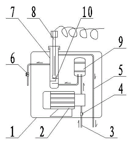
[0013] The present invention will be further described below with reference to the accompanying drawings.

[0014] figure 1 As shown, a solution sampling device includes a casing 1, a sampling pump 2, a solution inlet pipe 3, a filter 4, a solution outlet pipe 5, a sampling valve 6, a flow cell 7, an online detection device 8, a buffer tank 9 and a labyrinth gear board 10. The solution inlet pipe 3 is connected to the bottom side wall of the flow cell 7 through the filter 4, the sampling pump 2 and the buffer tank 9 in turn, the upper side wall of the flow cell 7 is communicated with the sampling valve 6, and the upper side wall of the flow cell 7 is communicated with the solution outlet pipe 5, The flow cell 7 is provided with an online detection device 8 and a multi-layer labyrinth baffle 10. The multi-layer labyrinth baffle is lower than the online detection device and the sampling valve, and higher than the connection between the solution inlet pipe and the flow cell...


PUM


Abstract

The invention relates to a solution sampling device which comprises a housing, a solution inlet pipe, a sampling pump, a flow cell, a sampling valve and a solution outlet pipe, wherein the sampling pump and the flow cell are arranged inside the housing; a solution inlet pipe is communicated with the lateral wall at the bottom of the flow cell via the sampling pump after passing through the outside of the housing; and the lateral wall of the middle-upper part of the flow cell is communicated with the sampling valve extending outside the housing, and the lateral wall of the upper part of the flow cell is communicated with the solution outlet pipe extending outside the housing. The device is simple and compact in structure, fast and safe to use, and capable of stably sampling and ensuring the accuracy of detected data.

Description

technical field [0001] The invention relates to a sampling device, in particular to a solution sampling device for timely monitoring the state of materials in fine chemical production. Background technique [0002] In the chemical production process, especially the fine chemical production, it is necessary to monitor the status of each material in a timely manner. When the material undergoes synthesis, reaction, concentration, acidification, leaching and other processes, it is also necessary to monitor the operating parameters of the reaction system of each process. The production site environment is complex, and there are toxic and harmful materials such as high temperature, high pressure, strong acid, and strong alkali. Opening sampling ports on the reactor, storage tank, and pipeline to conduct manual sampling is inconvenient to operate, time-consuming and laborious, and there is material liquid splashing and hurting people Security risks. [0003] The existing patent n...

Claims


Application Information

Patent Timeline
Patent Type & Authority Applications(China)
IPC IPC(8): G01N1/14
Inventor 唐洲李军秀闫国真杜长福张世青
Owner GEM JIANGSU COBALT IND CO LTD
Why Eureka
Try Eureka