
Honeycomb ceramic

A technology of honeycomb ceramic body and ceramic body, which is applied in the field of ceramics, can solve the problems of increasing the manufacturing cost and operating cost of a regenerative industrial furnace, and complicating the operation, so as to reduce the manufacturing cost and operating cost, and simplify the operation control system. Effect

Active Publication Date: 2012-10-24
山西科德垣环保材料有限公司
View PDF9 Cites 0 Cited by
  • Summary
  • Abstract
  • Description
  • Claims
  • Application Information

AI Technical Summary

Problems solved by technology

The reversing operation complicates the operation of high-temperature flue gas and low-temperature fluid, and increases the manufacturing and operating costs of regenerative industrial furnaces

Method used


Image

  • Honeycomb ceramic
  • Honeycomb ceramic
  • Honeycomb ceramic

Examples


Embodiment 1

[0021] 62 kg of sintered mullite, 16 kg of zirconia, 12 kg of kaolin, 1.5 kg of talcum powder, 1.5 kg of white corundum micropowder, 3.5 kg of binder, and 3.5 kg of paraffin, wherein the binder is composed of polyvinyl alcohol and cellulose by weight Prepared with a ratio of 45:55;

[0022] After mixing the above raw materials, add water with a weight of 35 kg of the mixture, fully mix and grind in a ball mill for 20 hours to make a slurry, pour the slurry into a mold after defoaming, and heat it to a temperature of 15°C. The slurry is naturally solidified and formed in the mold, and the formed green body is dried at 150°C for 10 hours, and then fired in a high-temperature furnace at 1380°C for 24 hours.

Embodiment 2

[0024] 85 kg of sintered mullite, 8 kg of zirconia, 3 kg of kaolin, 0.5 kg of talcum powder, 0.5 kg of white corundum micropowder, 1.5 kg of binder, and 1.5 kg of paraffin, wherein the binder is composed of polyvinyl alcohol and cellulose by weight 45:55 ratio composition;

[0025] After mixing the above raw materials, add water with a weight of 40 kg of the mixture, fully mix and grind in a ball mill for 25 hours to make a slurry, pour the slurry into a mold after defoaming, and heat it to a temperature of 105°C. The slurry is naturally solidified and formed in the mold, and the formed green body is dried at 180°C for 15 hours, and then fired in a high-temperature furnace at 1460°C for 36 hours.

Embodiment 3

[0027] 70 kg of sintered mullite, 17 kg of zirconia, 6 kg of kaolin, 1 kg of talcum powder, 1 kg of white corundum powder, 2.5 kg of binder, 2.5 kg of paraffin, wherein the binder is composed of polyvinyl propanol and cellulose by weight 45:55 ratio composition;

[0028] After mixing the above raw materials, add water with a weight of 36 kg of the mixture, fully mix and grind in a ball mill for 22 hours to make a slurry, pour the slurry into a mold after defoaming, and heat it to a temperature of 45°C. The slurry is naturally solidified and formed in the mold, and the formed green body is dried at 160°C for 12 hours, and then fired in a high-temperature furnace at 1400°C for 28 hours.


PUM


Abstract

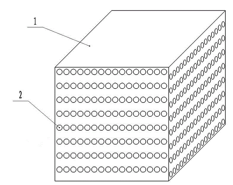
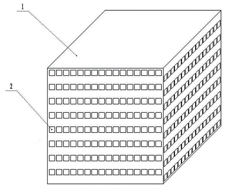
The invention provides a honeycomb ceramic capable of simplifying operation procedures. The honeycomb ceramic is provided with layered linear through holes which are formed inside the ceramic and parallelly distributed in the same layer, and a cross angle alpha is formed between axes of through holes in each two adjacent layers, is larger than or equal to 45 degrees and smaller than or equal to 90 degrees, and is preferably equal to 90 degrees. The honeycomb ceramic is directly mounted in a burner, fuel gas is respectively blown into the crisscross through holes, and hot waste gas is respectively sucked out of the crisscross through holes, so that heat of the hot waste gas is conducted to the fuel gas through the hole wall of the honeycomb ceramic to preheat the fuel gas. The honeycomb ceramic is provided with the structure with the crisscross through holes, air or fuel gas can be continuously supplied without reversing operation, accordingly, an air or fuel gas operation control system is greatly simplified, energy is saved, and the manufacturing cost and the operating cost of a heat accumulating type industrial furnace are reduced.

Description

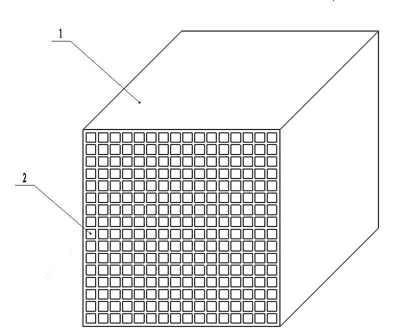
technical field [0001] The invention relates to ceramics, in particular to a honeycomb ceramic regenerator. Background technique [0002] At present, the regenerative combustion technology has been widely used in industrial furnaces, and the core component of the regenerator, the straight-hole honeycomb regenerator, has also been widely used. However, the current straight-hole honeycomb ceramic regenerator The structural form is a straight hole channel mode (such as figure 1 Shown), the layered distribution of straight holes is formed on the ceramic body, and the parallel arrangement on each layer. The regenerative body structure of this straight hole channel mode limits the air or gas control method of the regenerative combustion technology to only perform reversing operations within a specified time, that is, high-temperature flue gas and low-temperature fluid (air or gas) ) alternate in opposite directions through the regenerator combustion system. For example, when th...

Claims


Application Information

Patent Timeline
IPC IPC(8): F23D14/66F27D17/00C04B38/06C04B35/185
CPCY02E20/34
Inventor 张剑仲
Owner 山西科德垣环保材料有限公司
Learn More