Full-recovery shield tunnel enter and exit water stop device

A technology of water stop device and access hole, which is applied in shaft equipment, wellbore lining, tunnel lining, etc. It can solve the problems of not meeting construction conditions and anti-risk requirements, high requirements for ring pipe processing and embedding, and increased difficulty in construction operations, etc. , to achieve the effects of simple structure, improved construction efficiency, and convenient overall assembly and disassembly

Inactive Publication Date: 2012-10-24
上海盾构设计试验研究中心有限公司 +1
View PDF6 Cites 13 Cited by
  • Summary
  • Abstract
  • Description
  • Claims
  • Application Information

AI Technical Summary

Problems solved by technology

The disadvantages of this construction method are: if liquid nitrogen is used to freeze, the cost is high; if salt water is used to freeze, the construction period is long; and the processing and embedding of the ring pipe is high, easy to damage, and cannot be reused
[0007] In recent years, with the rapid increase in the demand for shield tunnels with large depth and cross-section, it has further increased the difficulty of the construction of large-depth, large-section ground reinforcement and shield entrance and exit openings on the retaining wall. The construction method of shield tunnel entry and exit is increasingly unable to meet the requirements of construction conditions and risk resistance

Method used


Image

  • Full-recovery shield tunnel enter and exit water stop device
  • Full-recovery shield tunnel enter and exit water stop device
  • Full-recovery shield tunnel enter and exit water stop device

Examples


Embodiment 1

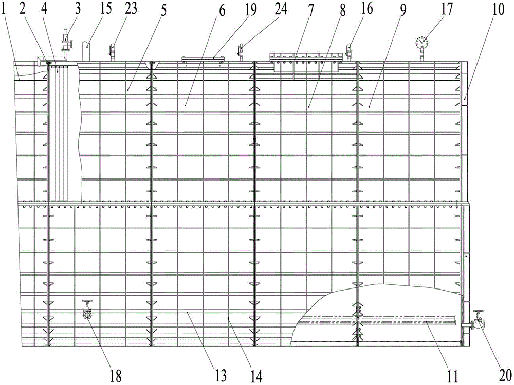
[0028] As a water stop device for the exit of the shield tunnel.

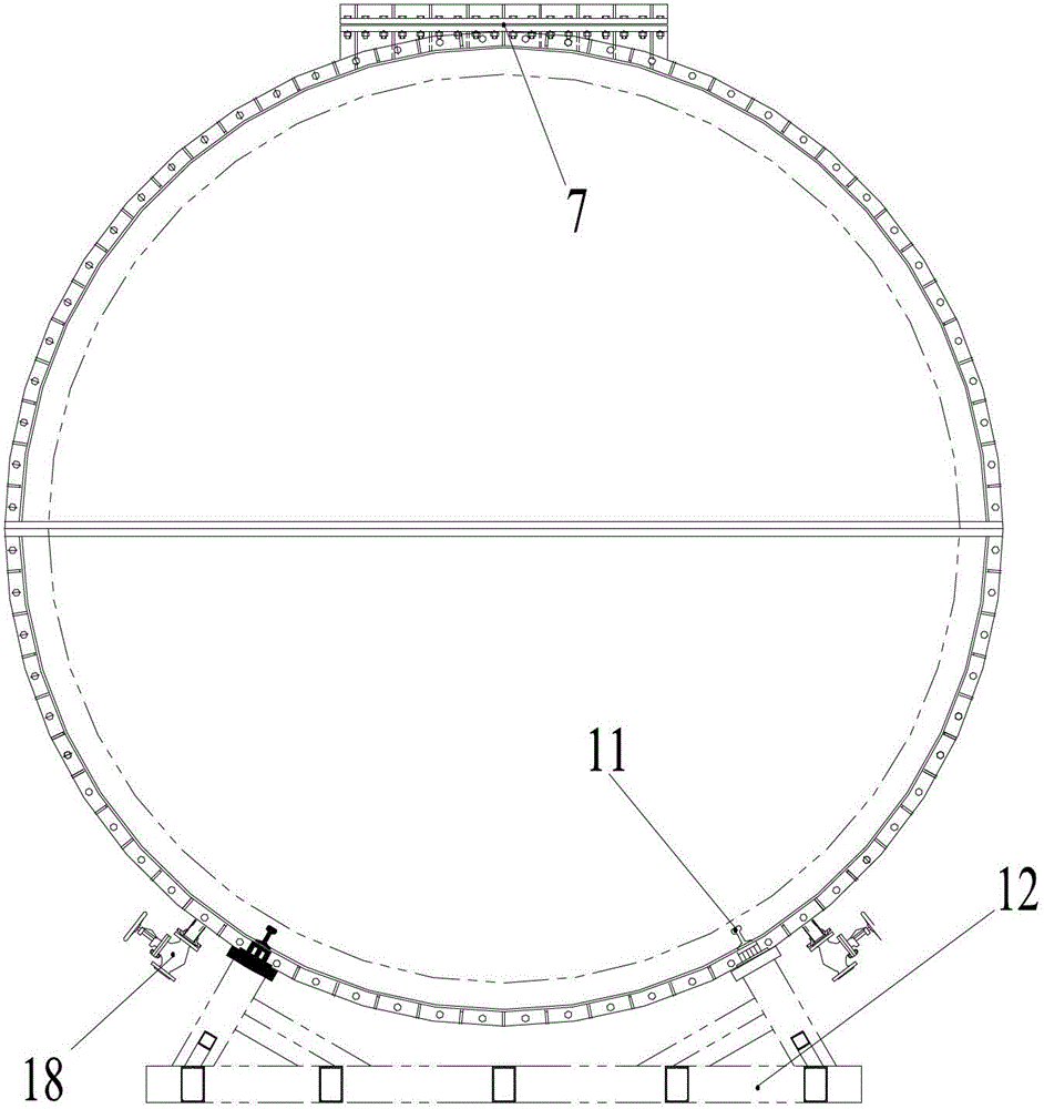
[0029] Step 1: Install the base 12 of the device. During the installation process of the device, a steel pad is used to level the base 12 and the standard cylinder group, so that the axes of the cylinders of the whole device are consistent.

[0030] The second step: air bag installation and grouting pipe installation. Install a circle of airbags in the hole close to the ground wall, and weld a circle of patterned steel plates on the outside of the airbags to narrow the gap between the hole circle and the shield; insert grouting pipes at the seams of the airbags to It is used for blocking the hole door.

[0031] The third step: installation of the transition cylinder 1 and the first standard cylinder 5 . Assemble the transition cylinder 1 and the first standard cylinder 5 on the ground, and the assembly adopts a horizontal assembly method. The specific method is to firstly assemble the upper and lower half cy...

Embodiment 2

[0036] Receive water stop device as shield tunneling.

[0037] Step 1: Install the base 12 of the device. During the installation process of the device, a steel pad is used to level the base 12 and the standard cylinder group, so that the axes of the cylinders of the whole device are consistent.

[0038] The second step: pre-cutting the door. The thickness of the connecting wall of the shield working well is 1.2m, and the shield is placed on the underground diaphragm wall, and the 80cm thick underground diaphragm wall is first cut out.

[0039] The third step: air bag installation and grouting pipe installation. Install a circle of airbags in the hole close to the ground wall, and weld a circle of patterned steel plates on the outside of the airbags to narrow the gap between the hole circle and the shield; insert grouting pipes at the seams of the airbags to It is used for blocking the hole door.

[0040] Step 4: Install the transition cylinder 1 and the first standard cyl...

Embodiment 3

[0046] As a water stop device for the exit of the shield tunnel.

[0047] Step 1: Install the base 12 of the device. During the installation process of the device, a steel pad is used to level the base 12 and the standard cylinder group, so that the axes of the cylinders of the whole device are consistent.

[0048] The second step: air bag installation and grouting pipe installation. Install a circle of airbags in the hole close to the ground wall, and weld a circle of patterned steel plates on the outside of the airbags to narrow the gap between the hole circle and the shield; insert grouting pipes at the seams of the airbags to It is used for blocking the hole door.

[0049] The third step: installation of the transition cylinder 1 and the first standard cylinder 5 . Assemble the transition cylinder 1 and the first standard cylinder 5 on the ground, and the assembly adopts a horizontal assembly method. The specific method is to firstly assemble the upper and lower half cy...


PUM


Abstract

The invention relates to a full-recovery shield tunnel enter and exit water stop device which is a horizontally lain steel sleeve of which an inner cavity is filled with water. The full-recovery shield tunnel enter and exit water stop device is formed by sequentially connecting a transition barrel, a standard barrel group and an end cover in a sealed mode, wherein the transition barrel is connected with a hole circle of a tunnel portal; one end of the standard barrel group is connected with the transition barrel; the other end of the standard barrel group is connected with the end cover; the standard barrel group consists of a standard barrel or a plurality of standard barrels which are connected end to end in a sealed mode; a freezing pipe for filling a refrigerant medium is arranged in an inner cavity of the standard barrel group; the bottom of the inner cavity is provided with a guide rail for bearing a shield; the top of the standard barrel group is provided with a prepared hole, a water injection hole, an air vent, a discharge hole, a vent hole, a lifting hole and a pressure gauge; the bottom of the standard barrel group is provided with a base; the transition barrel is provided with an overflow valve; and the end cover is provided with a stop valve for draining water. The full-recovery shield tunnel enter and exit water stop device has two hole enter and exit water stop functions, has a simple structure and is convenient to assemble and disassemble; the shield can be totally recycled so as to save the construction cost; and the construction that the shield safely and rapidly enters and exits from a tunnel can be implemented.

Description

technical field [0001] The invention relates to tunnel construction equipment, in particular to a fully recoverable water-stop device for shield tunnel entry and exit, which belongs to the technical field of construction. Background technique [0002] Since the beginning of the 21st century, the rapid development of the world economy has accelerated urbanization, and the shield method has developed rapidly as a means of underground space development. [0003] The tunneling of the shield means that the shield machine is in the working well, starting from the shield main machine to be positioned, the cutter head cuts the soil forward and enters the soil layer, and excavates forward along the design line until the shield completely enters the interval tunnel, and the opening reaction frame The entire construction process up to the removal of negative ring segments. Shield tunneling refers to the construction process in which the shield machine arrives at the working shaft, com...

Claims


Application Information

Patent Timeline
Patent Type & Authority Applications(China)
IPC IPC(8): E21D11/38E21D9/06
Inventor 陆晓华蒋华钦吴惠明蒋宏亮朱敏明杨正何晓庄欠伟
Owner 上海盾构设计试验研究中心有限公司
Why Eureka
Try Eureka