
System and method for detecting motion state of ball mill

A technology of motion state and detection system, applied in the direction of vibration measurement in solids, measuring vibration, measuring devices, etc., to achieve the effect of simple structure of the detection system, simple structure, and not easy to be affected by the environment of the work site

Inactive Publication Date: 2012-10-24
SHANDONG UNIV OF TECH
View PDF8 Cites 23 Cited by
  • Summary
  • Abstract
  • Description
  • Claims
  • Application Information

AI Technical Summary

Problems solved by technology

However, in the prior art, there is a lack of detection technology for the motion state of the ball mill.

Method used


Image

  • System and method for detecting motion state of ball mill
  • System and method for detecting motion state of ball mill
  • System and method for detecting motion state of ball mill

Examples


Embodiment Construction

[0040] In order to make the technical means, creative features, goals and effects achieved by the present invention easy to understand, the present invention will be further described below in conjunction with specific diagrams.

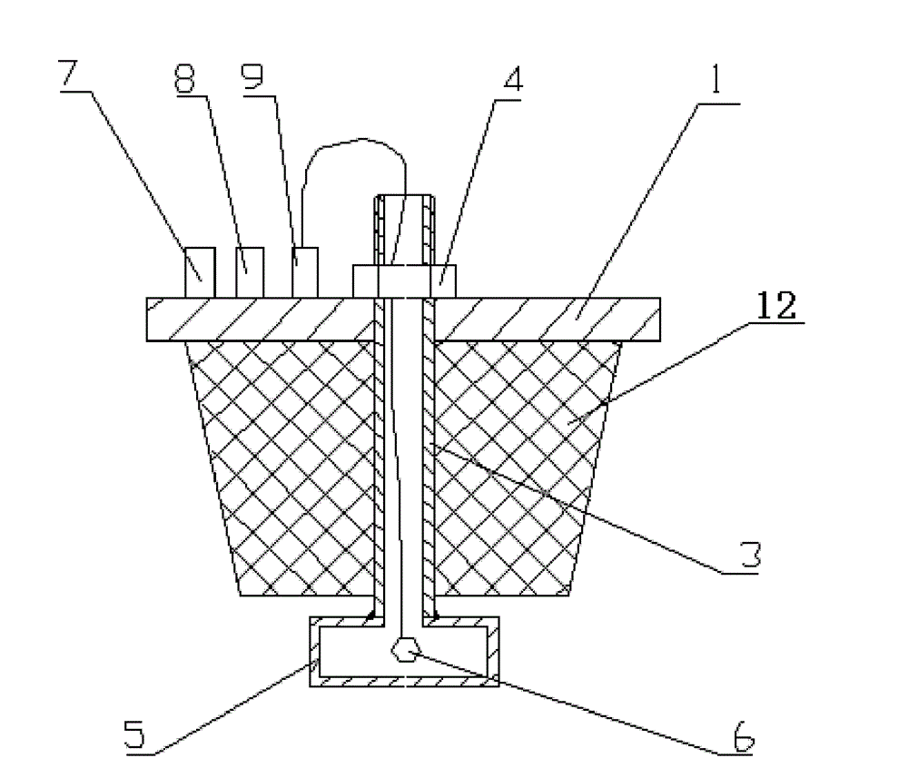
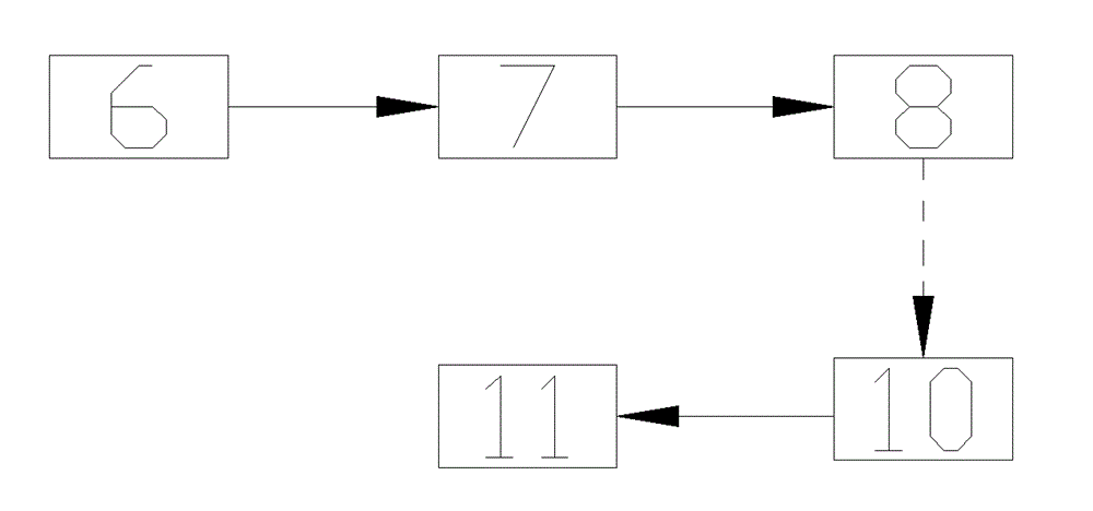
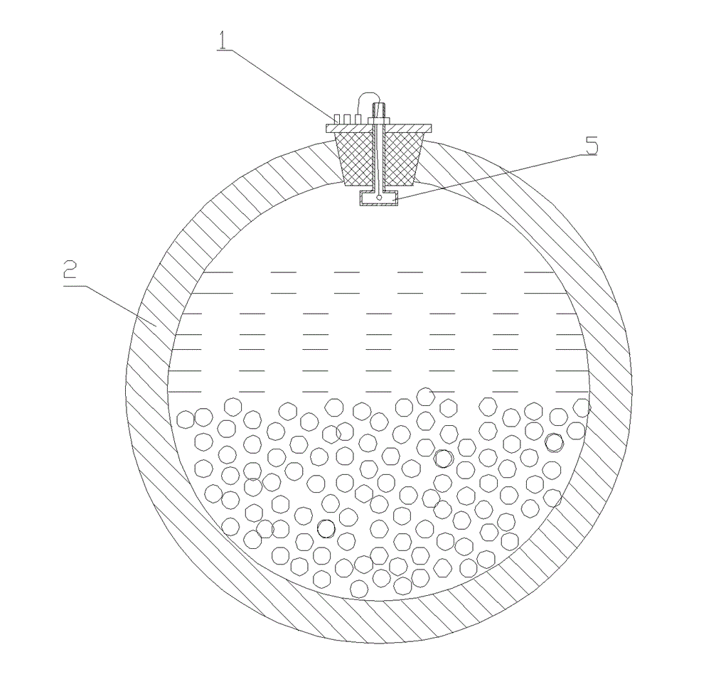
[0041] refer to figure 1 , figure 2 , ball mill motion state detection system, comprising a ball mill support, a ball mill main body 2 is arranged on the ball mill support, a ball mill cover 1 is arranged on the ball mill main body 2, a rubber pad 12 is arranged inside the ball mill cover 1, the rubber pad 12 is processed with a through hole, a The hollow screw 3 passes through the through hole, one end of the hollow screw 3 is fixedly connected to a resonance box 5, the resonance box 5 directly contacts the internal space of the ball mill main body 2, and the other end of the hollow screw 3 passes through the ball mill cover 1 and then is threaded to a nut 4. It also includes a sound detection device 6 for measuring the internal noise of the reson...


PUM


Abstract

The invention relates to the mechanical field of the milling engineering, and especially relates to a ball mill. A system for detecting the motion state of the ball mill comprises: a ball mill support, wherein the ball mill support is provided with a ball mill body, the ball mill body is provided with a ball mill cover, the inner side of the ball mill cover is provided with a rubber pad, the rubber pad is provided with a through hole, a hollow screw traverses through the through hole, one end of the hollow screw is fixedly connected with a resonance case, and the other end of the hollow screw is in threaded connection with a nut after traversing through the ball mill cover; a sound detection device arranged in the resonance case, wherein the sound detection device is connected with a signal processing device, and the signal processing device is connected with a wireless emission device; and a wireless receiving device which is connected with a display information processing circuit. Through adopting above technical scheme, the system allows the motion state of the ball mill body to be determined through detecting various noises in the ball mill body, has the advantages of simple structure and low cost, and is difficultly influenced by the onsite working environment.

Description

technical field [0001] The invention relates to the field of grinding engineering machinery, in particular to a ball mill. Background technique [0002] The ball mill is the key equipment for crushing and grinding after the raw materials are crushed. It is the most important high-fine grinding production equipment in industrial production enterprises. Inside the ball mill, there is a mixture of ball stones, raw materials and water. During the continuous working process of the ball mill, the ball stones will impact and grind the raw materials. As the fineness of raw materials increases, the mixing degree of raw materials and water becomes more and more sufficient. More and more solid raw materials are ground into fine particles, and more and more fine particles are suspended in the water to form mud. [0003] During the working process of the ball mill, when the ball mill always maintains a speed, the movement state of the ball inside the ball mill only achieves the best wor...

Claims


Application Information

Patent Timeline
Patent Type & Authority Applications(China)
IPC IPC(8): B02C25/00B02C17/18G01H1/00G01N29/02
Inventor 马立修刘伟申晋谭博学王雅静陈文钢孙霞孙贤明姜静
Owner SHANDONG UNIV OF TECH
Learn More