
Time measurement system and time measurement method

A technology of time measurement and time, which is applied in the field of measurement systems, can solve problems that affect the accuracy of time measurement, poor delay chain performance, and long time consumption, and achieve the effect of improving practicability

Active Publication Date: 2012-10-17
INST OF HIGH ENERGY PHYSICS CHINESE ACAD OF SCI
View PDF7 Cites 40 Cited by
  • Summary
  • Abstract
  • Description
  • Claims
  • Application Information

AI Technical Summary

Problems solved by technology

Therefore, not measuring the starting signal greatly reduces the usefulness of existing time measurement techniques
[0006] 2. This patent application uses the carry connection, LUT (Look-Up-Table, look-up table) and multi-bit adder inside the FPGA to construct the delay chain. The delay chain constructed is not uniform enough, and the poor performance of the delay chain will seriously Affects the accuracy of time measurement
[0007] This patent application uses binary search and pipeline technology to realize time encoding, which consumes a lot of FPGA logic resources and takes a long time to output measurement results

Method used


Image

  • Time measurement system and time measurement method
  • Time measurement system and time measurement method
  • Time measurement system and time measurement method

Examples


Embodiment approach

[0044] Please refer to Figure 4 , the preferred embodiment of the time measuring method of the present invention comprises the following steps:

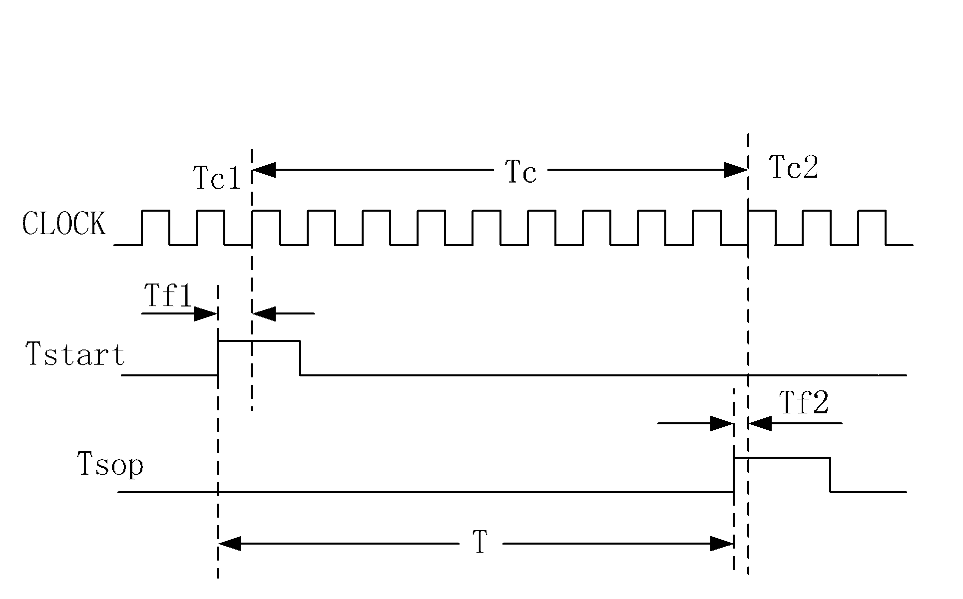
[0045] Step S1: one end of the first delay chain receives the start signal Tstart, so that the output of the delay unit receiving the start signal Tstart becomes the second level in turn, and each first register is input to the first delay chain after the start signal Tstart When the first clock edge of the reference signal is read, the output value of the first delay unit connected to it is read and the read data is saved, and the data converter converts the data saved in each register into time data, that is, the starting value is obtained Start signal fine time Tf1. The start signal fine time Tf1 is the time between the rising edge of the start signal Tstart and the first clock rising edge of the subsequent reference signal.

[0046] Step S2: one end of the second delay chain receives the timing signal Tstop, so that the output...


PUM


Abstract

The invention relates to a time measurement system, which comprises a start signal fine time measurement unit, a timing signal fine time measurement unit, a rough time measurement unit and a time calculation unit, wherein the start signal fine time measurement unit comprises a delay chain, a plurality of registers and a data converter; one end of the delay chain receives a start signal; outputs of delay units receiving the start signal are sequentially changed into second levels; each register reads and stores an output value of the corresponding delay unit at the rising edge of a first clock when the start signal is input; the data converter converts the stored data into time data to acquire start signal fine time; the timing signal fine time measurement unit is used for acquiring timing signal fine time; the working theory of the timing signal fine time measurement unit is similar to that of the start signal fine time measurement unit; the rough time measurement unit is used for measuring rough time under the driving of a field programmable gate array (FPGA) clock signal; and the time calculation unit is used for subtracting the timing signal fine time from a sum of the rough time and the start signal fine time to acquire time to be measured. According to the system, the precision and the instantaneity of time measurement are improved.

Description

technical field [0001] The present application relates to a measurement system, in particular to a time measurement system and method. Background technique [0002] High-precision time measurement technology needs to be applied in many fields of modern science and technology, such as telecommunications, laser ranging, satellite positioning, etc., especially in various fields of physics, such as nuclear physics, high-energy physics, medicine Fields such as image physics are inseparable from high-precision time measurement technology. Time measurement generally includes two parts: time discrimination and time-to-digital conversion (Time-To-Digital Converter, TDC). [0003] At present, high-precision TDC mainly includes ASIC (Application Specific Integrated Circuit, application specific integrated circuit), dedicated TDC chip, FPGA (Field Programmable Gate Array, field programmable gate array) and other implementation methods. The reason is that the scheme of implementing TDC...

Claims


Application Information

Patent Timeline
Patent Type & Authority Applications(China)
IPC IPC(8): G04F10/00
Inventor 王培林魏书军李道武帅磊丰宝桐胡婷婷孙芸华魏龙
Owner INST OF HIGH ENERGY PHYSICS CHINESE ACAD OF SCI
Learn More