
Method for machining cutter and dedicated mold

A processing method and mold technology, applied in the field of forging dies and tool forging dies, can solve the problems of uneven overall strength of the tool, easy bending of the forming tool, high processing cost, and achieve convenient workpiece fixation, improved yield, and uniform hardness. Effect

Inactive Publication Date: 2012-10-17
汉江工具有限责任公司
View PDF6 Cites 6 Cited by
  • Summary
  • Abstract
  • Description
  • Claims
  • Application Information

AI Technical Summary

Problems solved by technology

Usually, a formed tool needs 1.5-2.2 times the amount of bar material, and the man-hours for turning, milling, grinding, and quenching are also more, and waste products are unavoidable during quenching. Therefore, the overall processing cost is high and the processing efficiency is high. Low
In addition, because the carbide level of the existing high-speed tool steel bar is good on the surface and poor on the core, the metal grains closer to the core are less dense than the surface, and in the forming process of the tool, turning, milling, grinding What is lost is the dense part of the bar close to the outer carbide, leaving the edge of the blade as the tooth, but the part with poor carbide grade. Moreover, the chip flute produced by turning, milling and grinding also caused the overall damage of the tool. Inhomogeneous strength, therefore, the forming tool processed according to the prior art is easy to bend, chip and break

Method used


Image

  • Method for machining cutter and dedicated mold
  • Method for machining cutter and dedicated mold
  • Method for machining cutter and dedicated mold

Examples


Embodiment 1

[0019] A processing method for a gear shaping cutter, which comprises cutting a section of high-speed tool steel bar, the volume of which is greater than 3-5% of the volume of the gear shaping cutter to be processed, and its diameter is the same as that of the shaft of the forming gear shaping cutter. The diameter is the same. It is heated in a high-temperature furnace to a temperature suitable for forging, and then put into a special mold cavity with the same shape as the finished gear shaper for forging and pressing. After demoulding, it is milled and ground.

[0020] The above method is suitable for the processing of various metal cutting tools, but the cavities and models of the special molds are different.

Embodiment 2

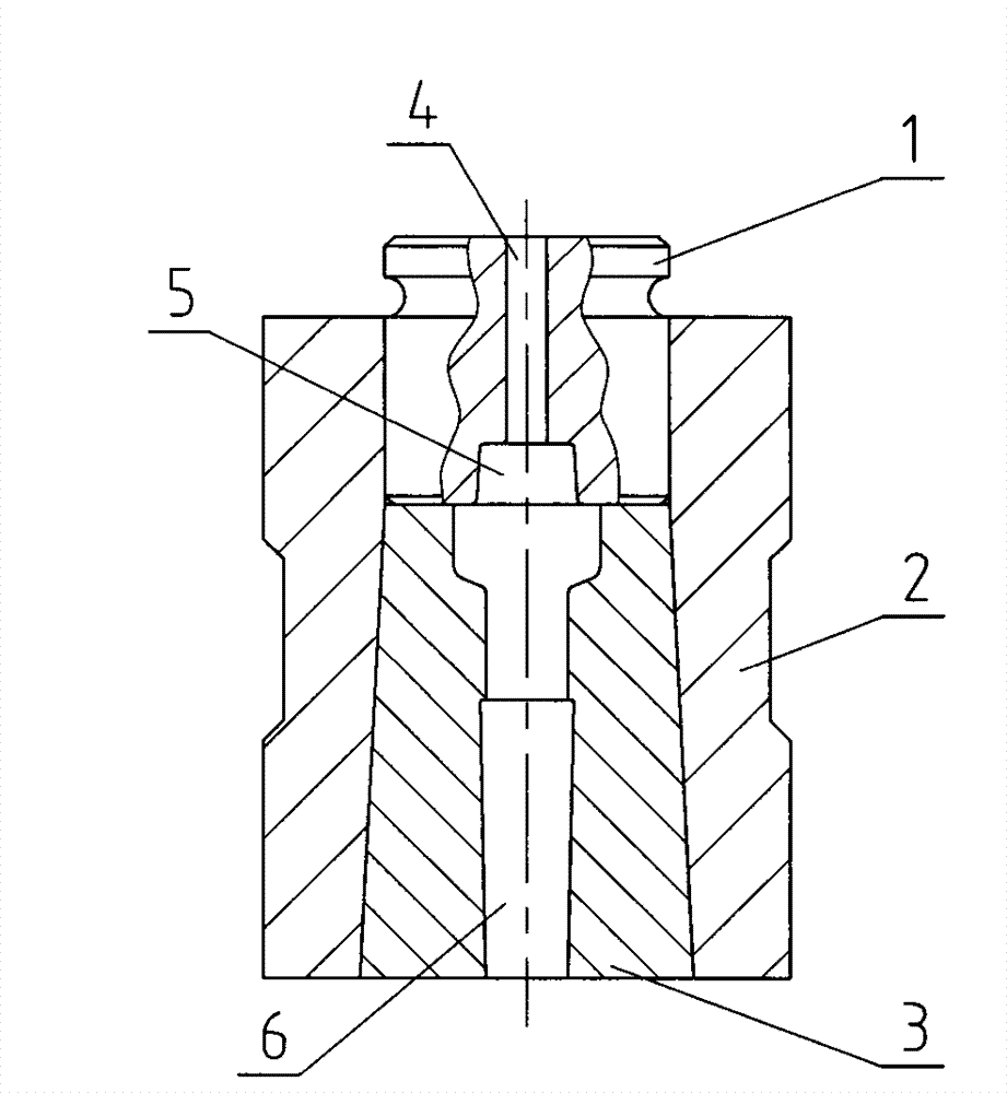
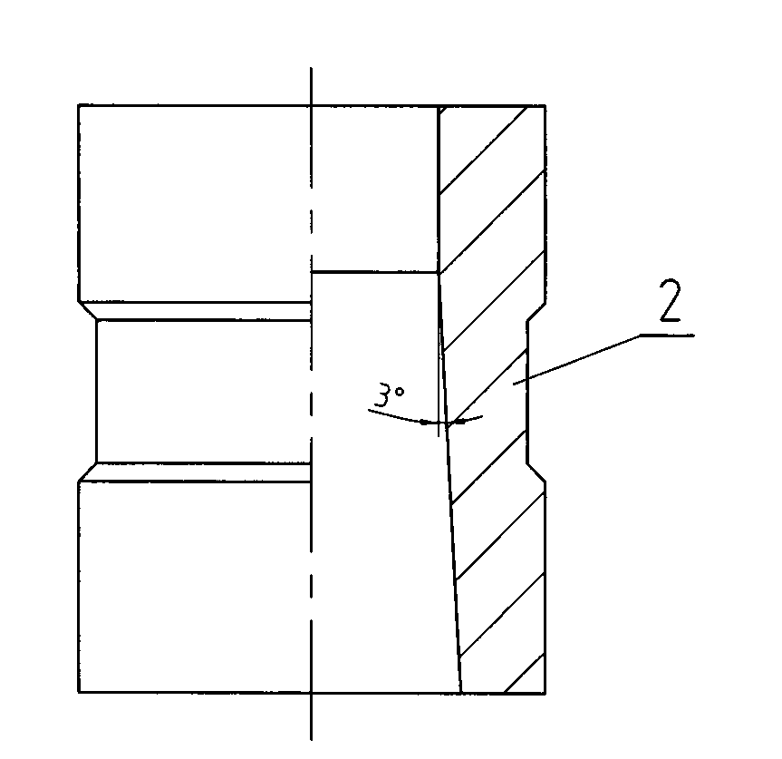
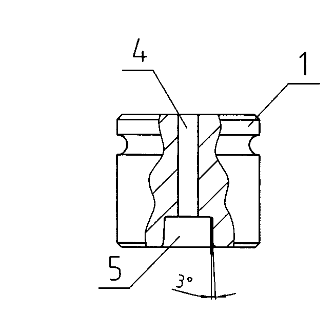
[0022] Such as Figure 1-5 As shown, the special mold used in the method of the present invention is made up of upper mold 1, lower mold 2 and die sleeve 3. The shape of the upper mold 1 is cylindrical, and the upper mold cavity 5 is conical with a small top and a large bottom, with a taper of 3°, or any angle within 2° to 5°; the lower mold cavity 6 and the main body shape of the forming tool The same, its shape is a conical shape with a small top and a big bottom, with a taper of 3°, or any angle within 2° to 5°; the inner wall of the mold sleeve 3 is matched with the outer wall of the upper mold 1 and the lower mold 2. The mold cavity 5 communicates with the exhaust hole 4, and the upper mold 1 can freely slide up and down on the upper section of the mold sleeve 3. This kind of mold is easy to fit and withdraw from the mold. During forging, the upper mold can be moved down conveniently. During the forging process of slightly thicker workpieces, the lower mold gradually mov...


PUM

PropertyMeasurementUnit
Taperaaaaaaaaaa
Taperaaaaaaaaaa

Abstract

The invention discloses a method for machining a cutter. The machining method comprises the following steps: heating a section of high-speed tool steel bar stock of which the diameter is equivalent to that of the rod part of a molded cutter to the temperature suitable for forging, placing the section of the high-speed tool steel bar stock into a dedicated mold cavity which has the same shape with the molded cutter for forging, demoulding the high-speed tool steel bar stock after molding, and further performing finish-milling and finish-grinding on the molded cutter. The invention also provides a dedicated mold used in the machining method. The dedicated mold consists of an upper mold, a lower mold and a mold sleeve, wherein the upper mold is cylindrical; the mold cavity of the lower mold is in the same shape with the main body of the molded cutter, and the lower mold is in the shape of a cone which is small at the top and large at the bottom; the inner wall of the mold sleeve is in clearance fit with the outer walls of the upper mold and the lower mold; the upper mold can slide up and down freely at the upper section of the mold sleeve. The method is suitable for machining various metal cutting tools. By adopting the method, the consumption of the bar stock is low, the milling and grinding workload is little, the rate of finished products is high, the quality of the molded cutter is better, and the service life of the mold cutter is longer; the dedicated mold is simple in structure, work piece is easily formed when in forging, moreover, the distribution of stress is uniform, and the withdrawal from the mold is convenient.

Description

technical field [0001] The invention relates to a processing method of a metal cutting tool, and at the same time relates to a forging die, especially a forging die of a cutting tool. Background technique [0002] At present, the processing method of metal cutting tools is to first turn and mill the high-speed tool steel bar to make it into the designed shape, then undergo quenching treatment, and finally carry out precision grinding and forming. Usually, a formed tool needs 1.5-2.2 times the amount of bar material, and the man-hours for turning, milling, grinding, and quenching are also more, and waste products are unavoidable during quenching. Therefore, the overall processing cost is high and the processing efficiency is high. Low. In addition, because the carbide level of the existing high-speed tool steel bar is good on the surface and poor on the core, the metal grains closer to the core are less dense than the surface, and in the forming process of the tool, turning,...

Claims


Application Information

Patent Timeline
IPC IPC(8): B23P15/28B21J13/02
Inventor 伍钢王银山张铭国
Owner 汉江工具有限责任公司
Features
  • Generate Ideas
  • Intellectual Property
  • Life Sciences
  • Materials
  • Tech Scout
  • Unparalleled Data Quality
  • Higher Quality Content
  • 60% Fewer Hallucinations
Learn More