
Keratoprosthesis

An artificial cornea and mirror column technology, applied in the medical field, can solve the problems of detachment surgery, poor fit of human eye tissue, failure, etc., and achieve the effects of firm fixation, reduced discomfort, and reduced weight

Inactive Publication Date: 2012-10-17
于好勇
View PDF0 Cites 7 Cited by
  • Summary
  • Abstract
  • Description
  • Claims
  • Application Information

AI Technical Summary

Problems solved by technology

In clinical practice, it is found that the stent of the artificial cornea is made of metal, which has a poor fit with the human eye tissue. As the stent is placed in the eye, the stent will slowly move to the outside of the eyeball, and may even fall off, causing the operation to fail.

Method used


Image

  • Keratoprosthesis
  • Keratoprosthesis
  • Keratoprosthesis

Examples


specific Embodiment 1

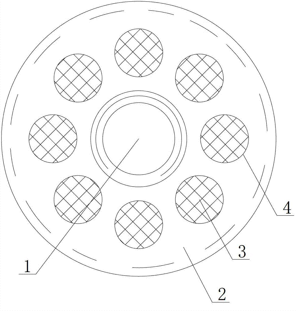
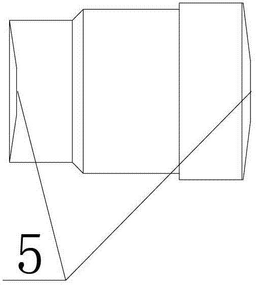
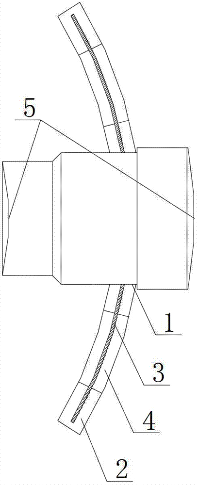
[0066] Such as Figures 1 to 3 As shown, the artificial cornea includes a bracket and a mirror column. The bracket is in the shape of a smaller part after a spherical surface is truncated by a reference surface. The center of the bracket is provided with a central hole 1; the inner wall of the central hole 1 is provided with internal threads; The bracket includes a main body 2 and a metal mesh 3 embedded in the main body 2; the extension direction of the metal mesh 3 is consistent with the extension direction of the main body 2; the outer wall of the mirror column is provided with an external thread matched with an internal thread.

[0067] The two sides 4 of the mirror column perpendicular to its axis are the structures of a smaller part of the sphere after being truncated by the reference plane perpendicular to the axis; and one of them protrudes away from the mirror column, and the other is toward the inside of the mirror column Recessed; when the bracket is matched with th...

specific Embodiment 2

[0069] The artificial cornea includes a bracket and a mirror column. The bracket is in the shape of a smaller part after a spherical surface is cut off by a reference surface. The center of the bracket is provided with a central hole 1; the inner wall of the central hole 1 is provided with internal threads; the bracket includes a main body 2 and the metal mesh 3 embedded in the main body 2; the extension direction of the metal mesh 3 is consistent with the extension direction of the main body 2; the outer wall of the mirror column is provided with an external thread matched with the internal thread.

[0070] The two sides 4 of the mirror column perpendicular to its axis are the structures of a smaller part of the sphere after being truncated by the reference plane perpendicular to the axis; and one of them protrudes away from the mirror column, and the other is toward the inside of the mirror column Recessed; when the bracket is matched with the mirror column, the protruding di...


PUM

PropertyMeasurementUnit
Diameteraaaaaaaaaa
Thicknessaaaaaaaaaa
Thicknessaaaaaaaaaa

Abstract

The invention relates to the field of medical treatment, and in particular relates to a keratoprosthesi. The keratoprosthesis comprises a frame and a cylindrical lens, wherein the frame is of a shape of a smaller part of a spherical surface which is cut off by a reference surface, and the center of the frame is provided with a central hole; the inner wall of the central hole is provided with internal threads; the frame comprises a main body and a metal net which is embedded in the main body; the extension direction of the metal net is consistent with the extension direction of the main body; and the outer wall of the cylindrical lens is provided with external threads which are matched with the internal threads. Compared with the prior art, according to the keratoprosthesi, the frame is designed in the way of comprising two parts of the main body and the metal net which is embedded in the main body, and because the human eye tissue and medical resin have higher compatibility, the human eye tissue can grow together with the main body, and cannot slowly push the main body to move towards the outside; but the medical resin material is crisper and lower structural strength, the structural strength of the frame can be improved through embedding the metal net into the frame, so the frame is not easy to be damaged.

Description

technical field [0001] The invention relates to the medical field, in particular to an artificial cornea. Background technique [0002] An artificial cornea is a device that replaces a person's living cornea. It is a substitute installed when a person's cornea is damaged due to various reasons and cannot be used for living corneal transplantation. [0003] It is suitable for patients with good fundus function and corneal damage who cannot undergo corneal transplantation. Including: 1) sports trauma, various diseases of the cornea itself, etc., patients with binocular failure due to repeated corneal transplant failures; 2) burns caused by fire, acid and alkali burns; Blind patients who are unable to undergo living corneal transplantation, and patients who have been blind for 2 to 30 years can be fitted with artificial corneas. [0004] The existing artificial cornea is generally made up of a bracket and a mirror column made of titanium alloy. In clinical practice, it is f...

Claims


Application Information

Patent Timeline
IPC IPC(8): A61F2/14
Inventor 于好勇
Owner 于好勇
Learn More