
Wireless energy double-frequency receiving device of sensor

A wireless energy and receiving device technology, applied in circuit devices, independent antenna unit combinations, antennas, etc., can solve the problems of low receiving efficiency and single receiving frequency band, and achieve the effect of improving conversion efficiency

Inactive Publication Date: 2012-10-10
JIANGSU UNIV
View PDF3 Cites 7 Cited by
  • Summary
  • Abstract
  • Description
  • Claims
  • Application Information

AI Technical Summary

Problems solved by technology

[0003] The current wireless energy receiving antenna is mainly implemented with a single-sided microstrip patch structure, which is characterized by a single receiving frequency band and low receiving efficiency

Method used


Image

  • Wireless energy double-frequency receiving device of sensor
  • Wireless energy double-frequency receiving device of sensor
  • Wireless energy double-frequency receiving device of sensor

Examples


Embodiment Construction

[0018] The technical solution adopted by the microwave energy receiving device proposed by the present invention is as follows.

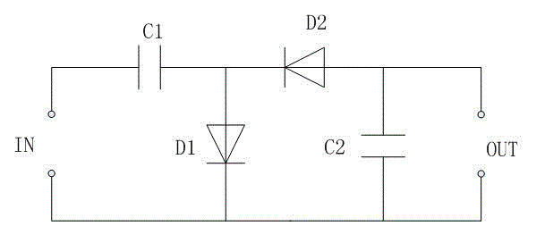
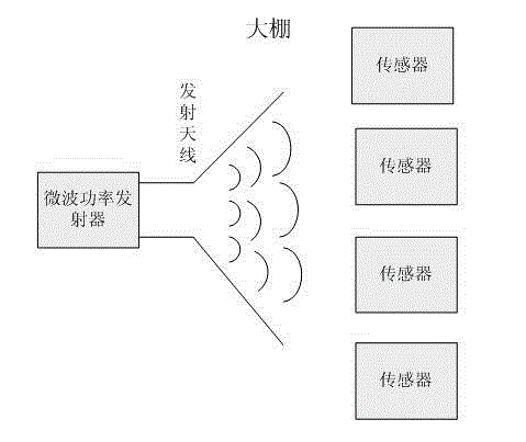
[0019] The receiving device consists of an antenna and a rectifying circuit. The antenna receives the transmitted microwave signal and transmits the microwave signal to the rectification circuit at the back, through which the high-frequency microwave signal is converted into a DC output to provide electrical energy for the sensor. The whole receiving device is designed on one PCB board.

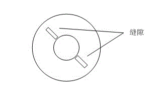
[0020] The antenna is implemented with a 3-layer metal general-purpose PCB board, and adopts a single-feed, double-sided common-ground microstrip patch structure. from Figure 4 The cross-sectional view is viewed from top to bottom. It can be seen that the PCB board is divided into 5 layers. The first layer, the third layer and the fifth layer are all copper materials. Except for the third layer as the ground plane, the other two layers are used for antennas. , ...


PUM


Abstract

A wireless energy double-frequency receiving device based on microwave transmission consists of a receiving antenna and a rectification circuit. The receiving antenna adopts a double-sided ground micro-strip line structure and is realized through a three-layer metal universal printed circuit board (PCB). The PCB is provided with five layers, wherein the first layer, the third layer and the fifth layer of the PCB are made of a copper material, the third layer is used as a ground wire, both the first layer and the second layer are used as the antenna and used for receiving electromagnetic waves of different frequency bands, and the radius and clearance of the two layers are different. The device can simultaneously receive the signal of a wave band s of 2.5 to 4GHz and a wave band c of 4 to 8GHz. Compared with other energy transmission systems, the wireless energy double-frequency receiving device has advantages of miniaturization, wide frequency band, high efficiency and the like.

Description

technical field [0001] The invention is a wireless energy dual-frequency receiving device based on microwave transmission, which can be applied to the energy supply of low-power sensors, and has the characteristics of wide frequency band and high efficiency. It belongs to the field of electronic information technology. Background technique [0002] At present, energy transportation mainly relies on vehicles or high-voltage power transmission equipment, which requires a lot of manpower and material resources, and there is still a lot of energy waste in the transportation process. Therefore, in the 1950s, people began to systematically study the use of microwaves to transmit energy. Under the advocacy of American Brown and others, the U.S. Air Force began to fund them to do some exploratory research in the early 1960s, and successfully demonstrated a helicopter driven by S-band (2.45GHz) microwave power in 1964. The aircraft directly extracts high-frequency energy from the m...

Claims


Application Information

Patent Timeline
Patent Type & Authority Applications(China)
IPC IPC(8): H02J17/00H01Q13/08H01Q1/38H01Q21/30H02J50/20H02J50/27
Inventor 徐雷钧杨晓东白雪
Owner JIANGSU UNIV
Learn More