Conductive particle
By forming a palladium layer with a moderate phosphorus concentration on the surface of the resin particles and combining it with insulating particles, the problem of migration of conductive particles and high cost in liquid crystal display devices is solved, and high conductivity and reliable connection between electrodes are achieved.
- Summary
- Abstract
- Description
- Claims
- Application Information
AI Technical Summary
Problems solved by technology
Method used
Image

Examples
no. 1 approach
[0051] (conductive particles)
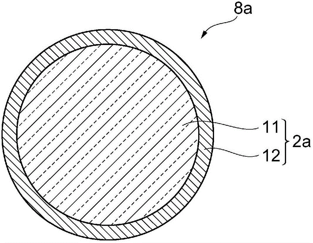
[0052] Such as figure 1 As shown, the conductive particle 8a according to the first embodiment of the present invention includes a core particle 11 and a palladium layer 12 covering the entirety of the core particle 11, a thickness of 20 nm to 130 nm, and a phosphorus concentration of 1% by weight to 10% by weight. Hereinafter, the conductive particles 8a according to the first embodiment are referred to as "mother particles 2a" as appropriate.
[0053]
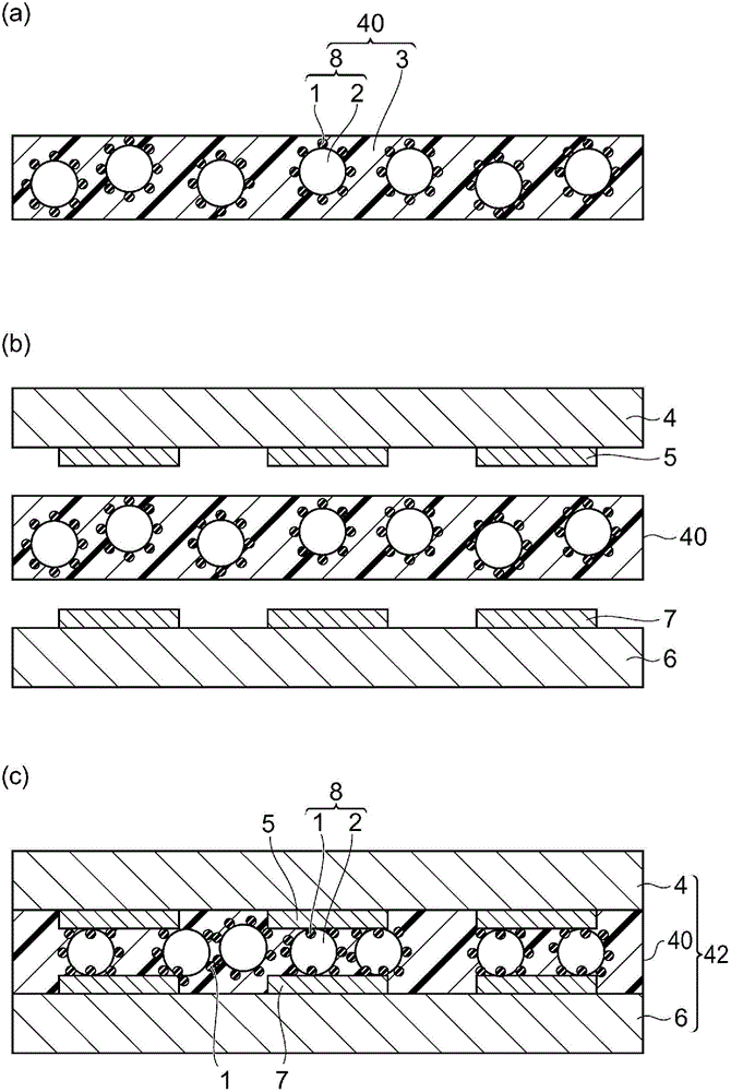
[0054] The particle size of the core particle 11 used in the present invention is preferably smaller than image 3 The minimum spacing between the first electrode 5 and the second electrode 7. In addition, when the height of the electrodes (interval between electrodes) varies, the particle size of the core particles 11 is preferably larger than the variation in height (the maximum interval between electrodes). For these reasons, the particle diameter of the core particle 11 is preferably 1...
no. 2 approach
[0066] Next, the electroconductive particle which concerns on 2nd Embodiment of this invention, and the manufacturing method of an electroconductive particle are demonstrated. In the following, only the points of difference between the above-mentioned first embodiment and the second embodiment will be described, and descriptions of the same matters between the two will be omitted.
[0067] (conductive particles)
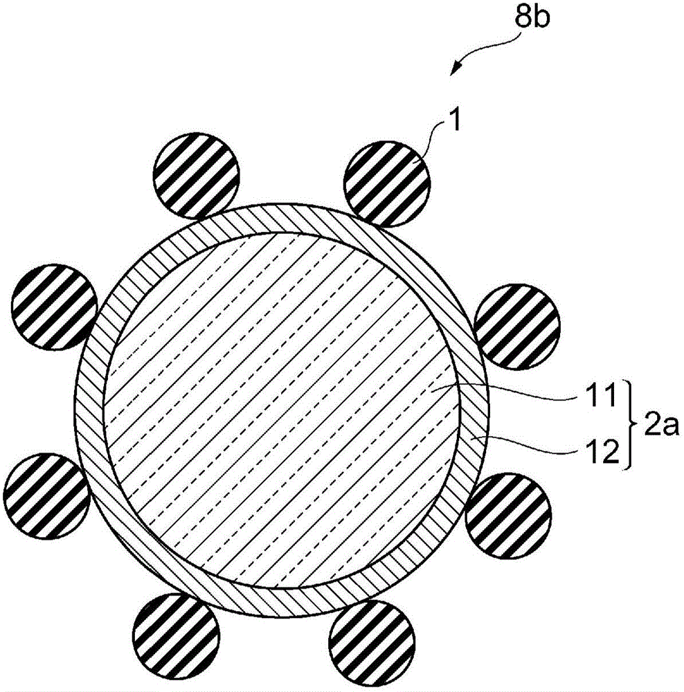
[0068] Such as figure 2 As shown, the conductive particle 8b according to the second embodiment not only includes the core particle 11 and the palladium layer 12, but also includes a plurality of insulating particles 1 arranged on the surface of the palladium layer 12. In this point, it is different from the first embodiment. The conductive particles 8a involved are different.
[0069]
[0070] The insulating particles 1 are preferably inorganic oxides. Assuming that the insulating particles 1 are organic compounds, the insulating particles 1 are deformed durin...
Embodiment 1)
[0172]
[0173] A copolymer of 10 g of phenoxy resin (manufactured by Union Carbide, trade name: PKHC) and acrylic rubber (40 parts of butyl acrylate, 30 parts of ethyl acrylate, 30 parts of acrylonitrile, and 3 parts of glycidyl methacrylate, Molecular weight: 850,000) 7.5 g was dissolved in 30 g of ethyl acetate to obtain a 30% by weight solution.
[0174] Next, 30 g of a liquid epoxy resin containing a microcapsule-type latent curing agent (epoxy equivalent of 185, manufactured by Asahi Kasei EPOXY Co., Ltd., trade name: NOVACURE HX-3941) was added to this solution, and stirred to prepare an adhesive solution.
[0175] 4 g of the conductive particles 1 prepared above were dispersed in 10 g of ethyl acetate.
[0176] In such a way that the conductive particles 1 are 37% by weight relative to the adhesive, the above-mentioned particle dispersion is dispersed in the adhesive solution, and the solution is coated on the spacer (siloxane-treated polyparaphenylene) wi...
PUM
| Property | Measurement | Unit |
|---|---|---|
| particle diameter | aaaaa | aaaaa |
| particle diameter | aaaaa | aaaaa |
| particle diameter | aaaaa | aaaaa |
Abstract
Description
Claims
Application Information
 - Generate Ideas
- Intellectual Property
- Life Sciences
- Materials
- Tech Scout
- Unparalleled Data Quality
- Higher Quality Content
- 60% Fewer Hallucinations
Browse by: Latest US Patents, China's latest patents, Technical Efficacy Thesaurus, Application Domain, Technology Topic, Popular Technical Reports.
© 2025 PatSnap. All rights reserved.Legal|Privacy policy|Modern Slavery Act Transparency Statement|Sitemap|About US| Contact US: help@patsnap.com